Ab der Version „Smap3D Plant Design 2016“ ist der Component Wizard verfügbar. Dieser Assistent führt einen Anwender komfortabel durch die notwendigen Schritte, um aus einem normalen 3D CAD-Modell eine Komponente für Smap3D Plant Design zu machen. Dabei wird die CAD-Einzelteildatei in mehreren Schritte interaktiv mit den benötigten Anschlusspunktdefinitionen und Datei-Eigenschaften aufbereitet, um diese im Anschluss direkt für die in der Version 2016 enthaltene zusätzliche Normteilverwaltung „File System“ zur Verfügung zu stellen.
Erste Schritte mit dem Component Wizard
- Standardmäßig ist der Wizard im Windows Startmenü CAD-Partner > Smap3D Plant Design 2016 > Admin Tools verfügbar.
- Wurden die Smap3D Toolbars (= Plant Design Administrator) installiert, dann ist die dazugehörige Schaltfläche im Normalfall in der Einzelteilumgebung Ihres CAD-Systems verfügbar.
- Bei der Erstellung oder Bearbeitung von Rohrklassen im Rohrklasseneditor mit aktiver zusätzlicher Normteilverwaltung „File System“ wird ein Anwender gefragt, ob er eine bestehende Plant Design Komponente verwenden oder eine neue mit dem Component Wizard aufbereiten möchte.
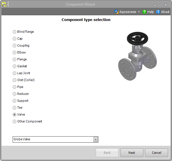
1. Auswahl des Komponententyps
Im ersten Schritt muss ein Anwender auswählen, welchem Komponententyp das aktive 3D CAD-Modell entspricht.
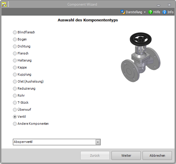
Tipp: In der Version „Smap3D Plant Design 2016“ werden nur Einzelteildateien unterstützt.Für Baugruppendateien empfehlen wir weiterhin die Verwendung des Coordinate System Wizard.
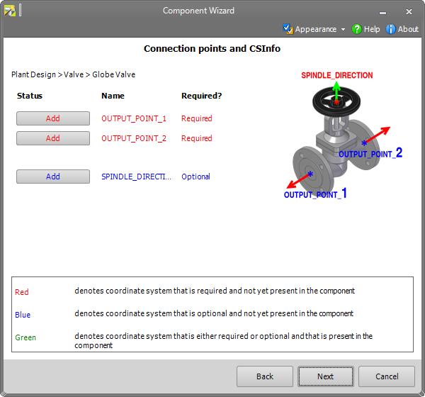
2. Anschlusspunkte und CS Info
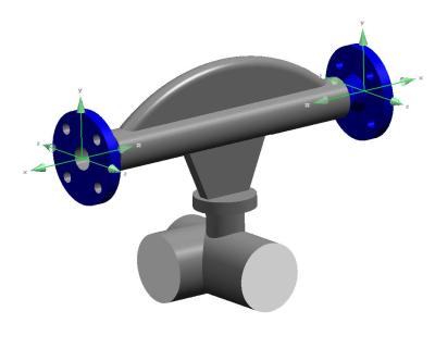
Nun müssen die für den gewählten Komponententyp notwendigen Anschlusspunktdefinitionen am 3D-Modell erzeugt werden.
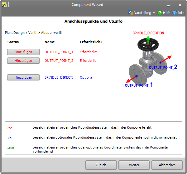
Mit den Schaltflächen „Hinzufügen“ wird der „Coordinate System Wizard“ gestartet. Die verfügbaren Optionen werden gefiltert auf die passenden Parameter gemäß dem gewählten Komponententyp und dem jeweiligen Anschluss (Anschlussnummer).
Mit dem „Coordinate System Wizard“ muss nun die jeweiligen Anschlusspunktdefinitionen (= Koordinatensysteme und CSInfo-Eigenschaft) im 3D Modell erzeugt werden.
BEACHTEN SIE DABEI DIE JEWEILIGE ANSCHLUSSNUMMER, DIESE MUSS AN DIE PASSENDE GEOMETRIE BZW. POSITION IM 3D-MODELL ANGEBRACHT WERDEN.
Erst wenn alle Anschlusspunktdefinitionen (Schaltflächen) Grün dargestellt werden, sollte man mit „Weiter“ fortfahren.
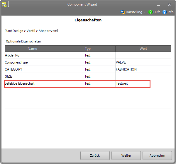
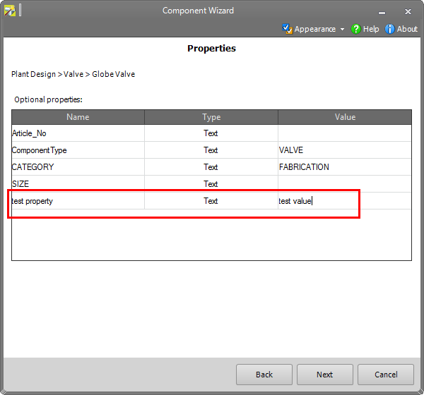
3. Eigenschaften
In diesem Schritt werden gemäß dem Komponententyp die „Benötigten“ und/oder „Optionalen Standardeigenschaften“ angezeigt. Werden „Benötigte Eigenschaften“ angezeigt, so muss ein Anwender die passenden Werte dazu eingeben. „Optional Eigenschaften“ könnten unausgefüllt bleiben. Wir empfehlen jedoch, so viel Informationen wie möglich für die Komponente zu hinterlegen, um diese ggf. für zukünftige Anforderungen vorzubereiten.
Neben den standardmäßig angezeigten optionalen Eigenschaften können noch weitere optionale Eigenschaften erzeugt werden (Funktionen dazu im Kontextmenü).
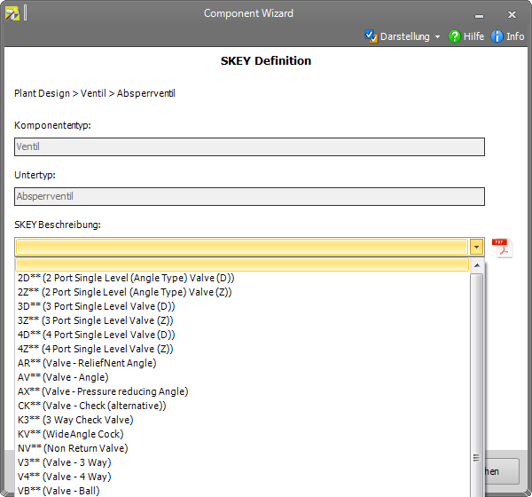
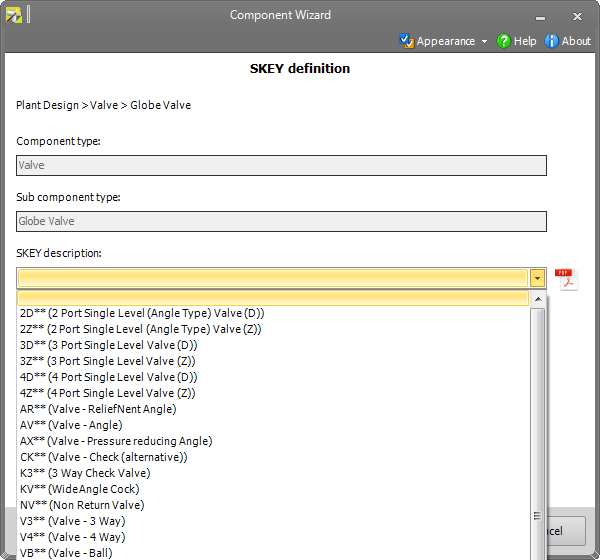
4. SKEY Definitionen
Jetzt kann optional die SKEY Definition für die Komponente durchgeführt werden, die für Smap3D Isometric benötigt wird. D. h. Ist kein Smap3D Isometric im Einsatz, so kann diese Eigenschaft leer bleiben. Je nach Komponententyp steht eine gefilterte Liste mit möglichen SKEY Werten zur Verfügung.
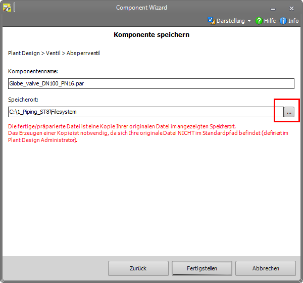
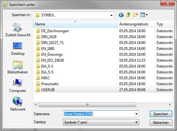
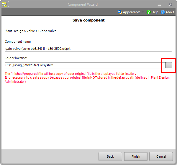
5. Komponente speichern
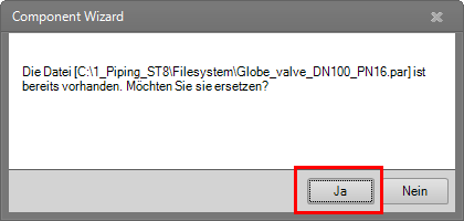
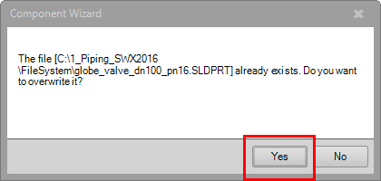
Zuletzt wird die aufbereitete Komponente gespeichert. Wurde die aktive 3D-Einzelteildatei bereits vor der Aufbereitung mit dem Component Wizard im Normteilordner für die zusätzliche Normteilverwaltung „File System“ abgespeichert (oder in einem beliebigen Unterordner), so wird dieser in der Zeile „Speicherort“ angezeigt. Durch Klick auf die Schaltfläche „Fertigstellen“ mit anschließender Bestätigung („JA“) wird die aktive 3D-Datei an diesem Speicherort überschrieben/ersetzt.
Wird für die aktive 3D Einzelteildatei ein Speicherort außerhalb des Normteilordner für die zusätzliche Normteilverwaltung „File System“ erkannt, so wird in roter Schrift eine zusätzliche Meldung im Fenster des Component Wizard angezeigt.
In der Zeile „Speicherort“ wird der im Plant Design Administrator eingestellte Normteilordner für die zusätzliche Normteilverwaltung „File System“ angezeigt. Mit der rechten Schaltfläche kann dieser Speicherort zu einem darin befindlichen Unterordner geändert werden.
Durch Klick auf die Schaltfläche „Fertigstellen“ wird eine Kopie der aktiven 3D-Datei am eingestellten Speicherort gespeichert.
Die mit dem Component Wizard durchgeführte Aufbereitung ist in diesem Fall nur in der Kopie vorhanden. Die originale Datei (außerhalb des Normteilordners) wird dabei nicht geändert.
 Druck
Druck
.jpg)
.jpg)


.jpg)