The following requirements apply to ‚finishing components‘ in Smap3D Piping for Solid Edge®, i.e. components which are meant to be built at the ends of pipelines.
Finishing components are for example, blind flanges, caps, etc.
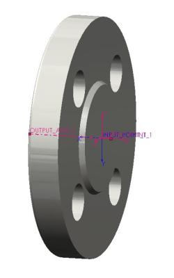
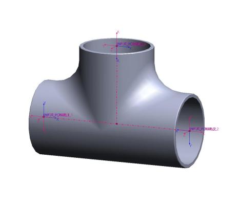
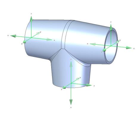
Only the side where the pipe should end needs an ‚INPUT_POINT‘ and an ‚OUTPUT_POINT‘.
 If such a component is built into a pipeline, a pipe will not be separated to create two pieces of pipe: instead the pipe is cut and closes at the point of this ‚finishing‘ component.
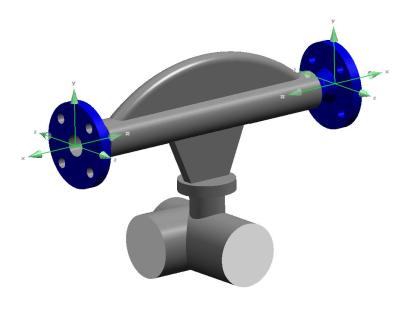
The proper coordinate systems can be created and ‚CSInfo‘ can be defined easily using Coordinate System Wizard.
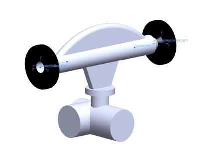
Example:
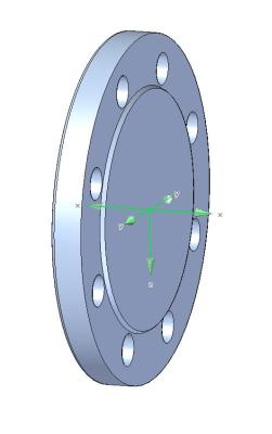
A blind flange has only one side where the pipe connects.
This component has only one input and one output option.
This is the only side which needs to be given an ‚INPUT_POINT‘ and an ‚OUTPUT_POINT‘.
![]() The X axis of each coordinate system must always point in the direction of the INPUT or OUTPUT.
The X axis of each coordinate system must always point in the direction of the INPUT or OUTPUT.
Since Plant Design 2016 you can use the Component Wizard for an easy and fast creation of such components:
The Component Wizard
 Druck
Druck