Wie werden in Smap3D P&ID Symbole aus anderen Programmen importiert?

Klarer Fall: Wer möchte schon sämtliche Symbole in Smap3D P&ID neu zeichnen, die mit der alten P&ID Software erstellt wurden? Aus diesem Grund stellt Smap3D P&ID eine Möglichkeit zur Verfügung, wie sie importiert werden können.

Ein Video (englisch) über den Import von Symbolen aus anderen Programmen finden Sie auch in unserem YouTube-Channel.

Vorgehensweise

1. Als erstes müssen Sie die Symbole, die Sie verwenden wollen, als .dxf- oder .dwg-Datei aus dem ursprünglichen CAD-Programm exportieren.

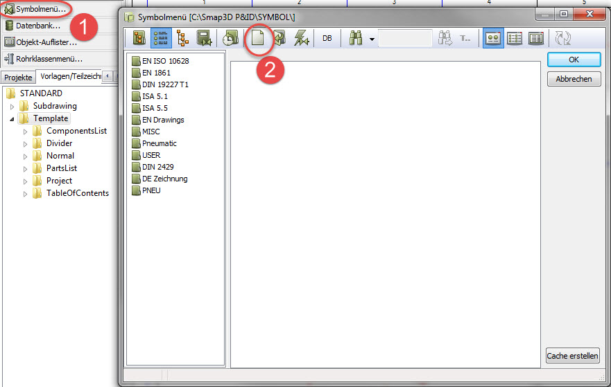
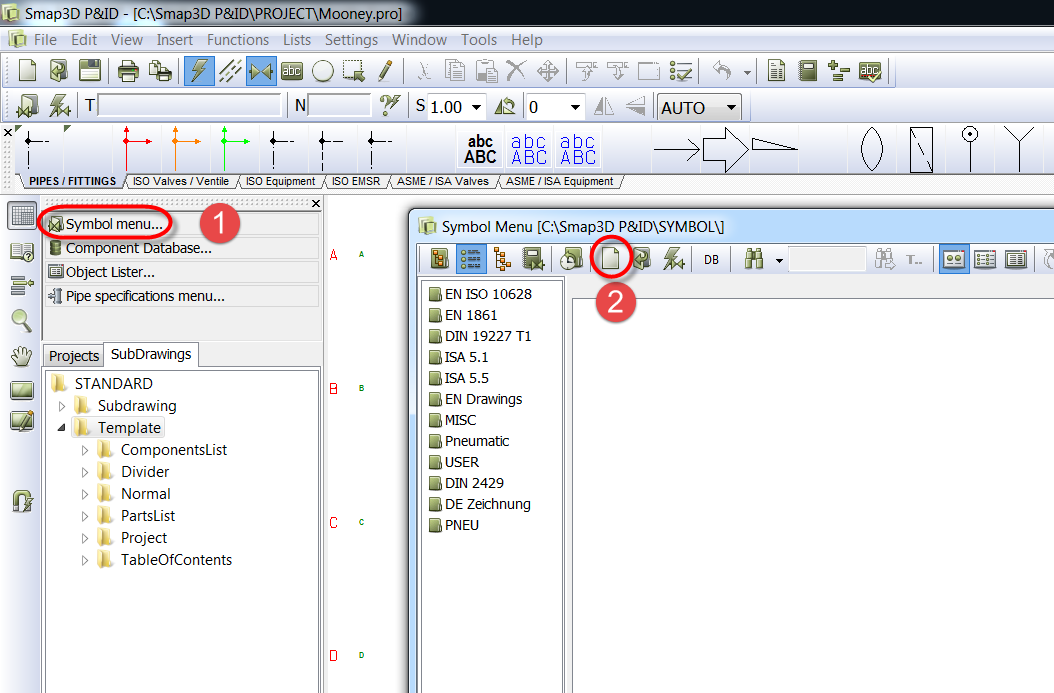
2. Öffnen Sie nun in Smap3D P&ID das Symbolmenü und klicken Sie auf den „Neues Symbol zeichnen“ Button.


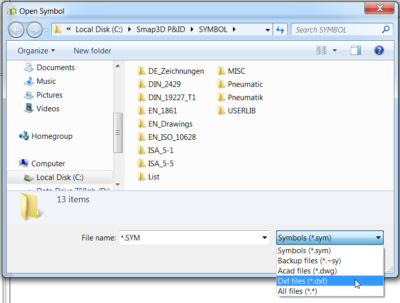
3. Nun können Sie die Datei aus dem Punkt 1 importieren. Dazu gehen Sie auf DateiÖffnen.

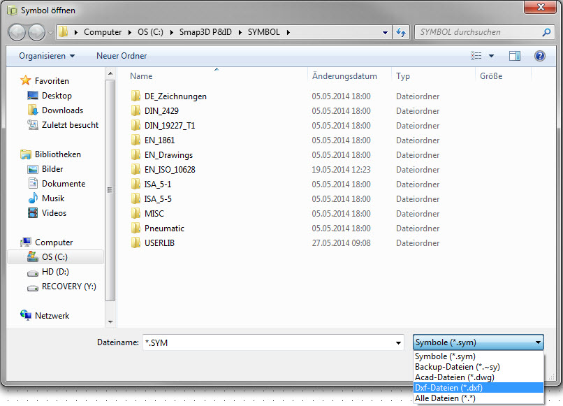
4. Ändern Sie den Dateityp zu .dxf oder .dwg, abhängig davon, welchen Dateityp Sie im Punkt 1 gewählt haben. Öffnen Sie die Datei.


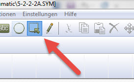
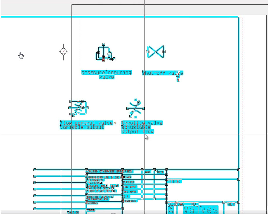
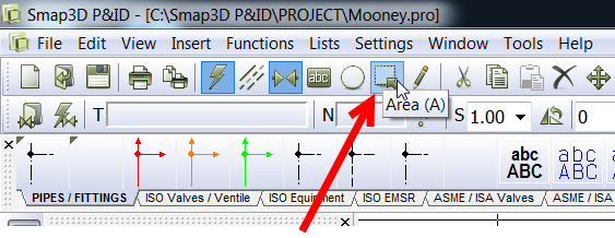
5. Benutzen Sie das Tool „Bereiche“, um jede ungewünschte Geometrie vom Symbol zu entfernen. In unserem Beispiel sehen Sie, dass wir den Zeichnungskopf und einige zusätzliche Symbole löschen müssen.

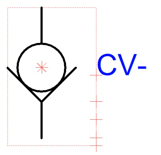
6. Positionieren Sie die Textfelder und verschieben Sie den „Referenzpunkt“ auf die gewünschte Position. Der Referenzpunkt wird als Einfügepunkt, wenn das Symbol platziert wird. Es ist auch der Drehpunkt, wenn Sie das Symbol rotieren.

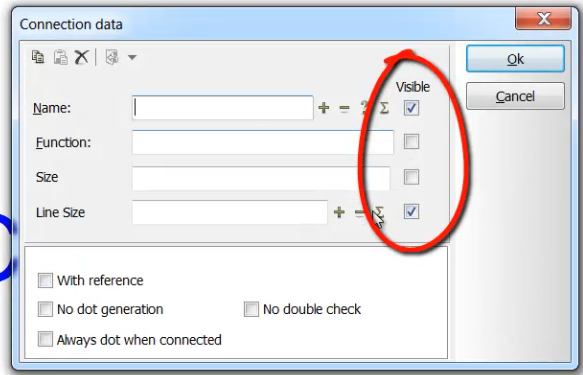
7. Fügen Sie Anschlusspunkte ein, wo Sie sie benötigen und stellen Sie sicher, dass Sie die Sichtbarkeit der Attribute richtig einstellen. In unserem Beispiel möchten wir z.B. nicht den Namen des Anschlusses und die angeschlossene Leitungsgröße im Diagramm später sehen. Also entfernen wir die beiden Haken.

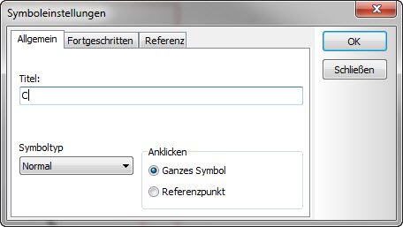
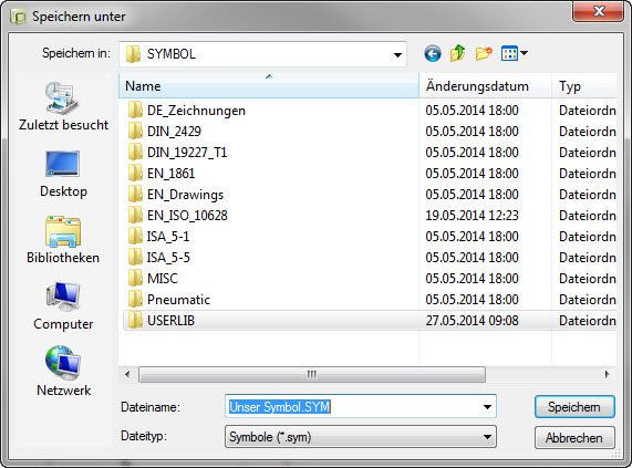
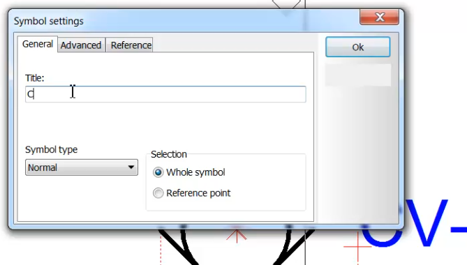
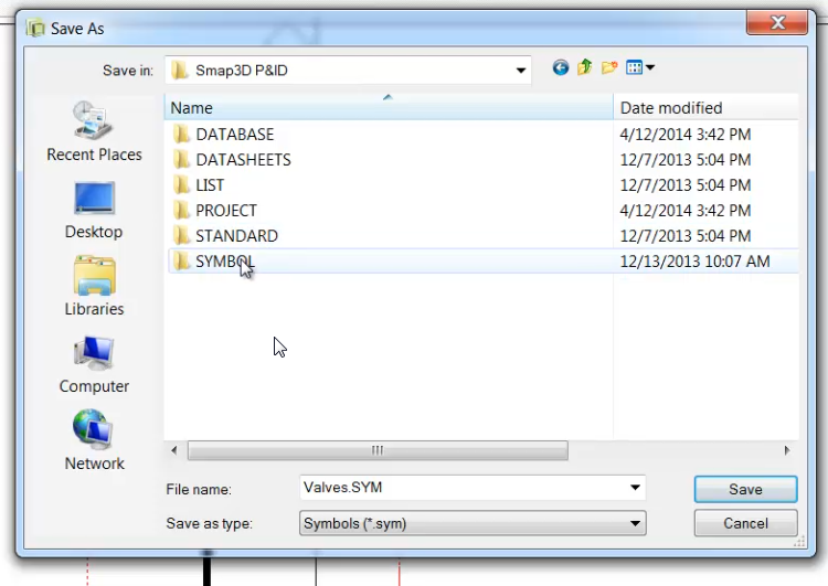
8.    Speichern Sie das Symbol ab. Das erste Mal werden Sie aufgefordert einen Titel, den Speicherort und den Dateinamen festzulegen. Sie können das Symbol zu einer bestehenden Bibliothek hinzufügen oder wie in unserem Fall, speichern wir es im Ordner „UserLib“. Ihr Symbol kann nun im Diagramm verwendet werden.


Druck Druck

What is new in Smap3D Plant Design version 12?

The most important improvements in version 12 of Smap3D Plant Design are:

General

– New setup option Default configuration and Data

– Usage of Licensing 2.2

P&ID

– New and updated standard symbols

– New function to create and handle object groups

– New line data fields to enhance the line article data

– New module Project generator


Pipe specification editor

– New pipe specification header

– New status for pipe specifications

– New application Pipe Specification search


3D Piping

– New functions Recalculate region and Refresh region

– New QuickPlace method for Coupling

– New QuickPlace method for Slope component

– New application VC Writer

– Redesign of To-Do list with new filter and structuring functions


Isometric

– Support of the P&ID function Reference designation

– Enhanced file name generator for isometric drawings


Druck Druck

Einrichtung Ihrer ISO Orientierung für SOLIDWORKS

Wie lässt sich die Orientierung der Zeichnung nachträglich im Isometric ändern?

In der Vergangenheit war es notwendig, Ihre Solidworks-Baugruppe in einer eher ungewohnten Ansicht zu erstellen, um eine korrekte Orientierung in den Isometric Zeichnungen zu erhalten. Ab sofort entfällt die Voreinstellung der Orientierung in SOLIDWORKS und Sie brauchen damit jetzt auch keine “spezielle” Vorlage in SOLIDWORKS für Smap3D Piping. Weiterlesen

Druck Druck

Adjusting your ISO orientation for SOLIDWORKS

In the past it was necessary to build your SOLIDWORKS Assembly in an unorthodox view orientation so that your Single Line Isometric Drawings (ISOGEN) would be in the correct orientation. Well a couple of releases back we have resurrected that situation. There is now more options for you to freely control the output of you ISO drawings without doing anything more than choosing a different option from the Smap3D Isometric settings menu. Let’s look at exactly where this setting is.

Go to Start, All Programs, CAD Partner, Smap3D Plant Design, and click on Isometric.


With Smap3D Isometric open you now have access to open the options, which is in the Tools pull-down menu.

Open ISO options

From here you have access to change the “Up/North direction”. Notice all of the options that are available now.

New available direction settings

Below you will see the preferred setting for use with SOLIDWORKS.

Correct setting for SolidWorks

Druck Druck

Was ist neu in Smap3D Plant Design Version 12?

Die wichtigsten Neuerungen in Version 12 von Smap3D Plant Design sind:

Allgemeine Neuerungen

– Die neue Setup-Option Standardkonfiguration und Daten

– Verwendung von Licensing 2.2

P&ID

– Neue und aktualisierte Symbolnormen

– Neue Funktionen zur Erstellung und Handhabung von Objektgruppen

– Neue Liniendatenfelder zur Erweiterung der Liniendaten

– Neues Modul Projektgenerator


Rohrklasseneditor

– Neue Rohrklasseneigenschaften

– Neuer Status für Rohrklasse

– Neues Modul Rohrklassensuche


3D Piping

– Neue Funktionen Bereich neu berechnen und Bereich aktualisieren

– Neue QuickPlace Methode für Kupplung

– Neue QuickPlace Methode für Gefälle

– Neues Programm VC Writer

– Redesign der To-Do Liste mit neuen Filter- und Strukturierungsfunktionen


Isometric

– Support der P&ID Funktion Referenbezeichnung

– Verbesserter Dateinamengenerator für Isometriezeichnungen

Druck Druck

Conversion of Smap3D standard and repetition parts for SOLIDWORKS 2015

In SOLIDWORKS 2015, there is a breaking change causing 3rd party data loss when saving a document with SOLIDWORKS 2015.
Smap3D applications use this 3rd party data storage streams to hold some information.

Therefore it is important and inevitable to perform the Smap3D parts conversion with the Smap3D SOLIDWORKS 2015 conversion tool to save Smap3D data storage (standard and repetition parts) before starting to work with Smap3D parts in SOLIDWORKS 2015 or its future versions.

In this PDF document the workflow is described step by step:
Conversion of Smap3D parts for SolidWorks 2015

Video instruction:
Video guide to converter tool for SolidWorks 2015

Druck Druck

Konvertieren von Smap3D Norm- und Wiederholteilen für SOLIDWORKS 2015

Mit SOLIDWORKS 2015 wurde eine grundlegende Änderung in der SOLIDWORKS Dateistruktur vorgenommen.
Diese verursacht, dass Informationen von Drittanbietern in den Dateien verloren gehen, sobald man diese mit SOLIDWORKS 2015 speichert.
Die Smap3D Plant Design Anwendungen nutzten bisher diese Speicherstruktur für Drittanbieter, um für Smap3D Plant Design notwendige Informationen bereitzustellen. Weiterlesen

Druck Druck

How do I make line link symbols available?

Have you ever tried to make a new Line link symbol, but the symbol you want to use is not in the drop down list?

But it is in your symbol menu, it may even be in the same folder as the ones currently in the drop down menu as I have shown below.

To make more or newly created line link symbols available in the drop down menu follow these steps:

Go to the Settings pull down menu in Smap3D P&ID, click on “Text/Symbol defaults”.

In the middle of that new window you will see a section labled “Symbol defaults”, select the radio button for “Line link symbols”. To the right of that area now you will be able to click the drop down box to view what symbols are currently active. Just below the drop down box, you will see 2 buttons, “New” and Delete”. Use the “New” button and browse to location and to the sybmol you wish to add.

Then browse to the location of the symbol in the symbol menu you wish to add to the list. I’m going to add 2 symbols.

Now you will find the in the drop down list the next time you try to make a new Line Link.


To remove a symbol from the list simply choose it from the drop down box, then click on “Delete”. Use this same technique to control the default symbols used for Primary header (titleblock), Secondary header, Line link names, and Symbol datafields.

Druck Druck

How do I use the P&ID symbols I have created in another CAD program?

Problem: I don’t want to recreate the symbols I have already created once in my old P&ID software again in Smap3D. How do I import them so I can use them in Smap3D P&ID?

Click here to see a detailed video

1. First you will need to export the symbol(s) you wish to use in Smap3D to a .dxf or .dwg-file from the native CAD program.

2. Now from Smap3D open the symbol menu and click on the button to create a new symbol.

3. Now you are ready to import the file from step 1. Go to the file pull down menu and click on “Open”.

4. Change the file type to DXF or DWG depending on which type you exported to in step 1 and open it.

5. Use the area select tool to delete any unwanted geometry from the symbol. You see in my example that I have extra symbols and the title block to remove.

6. Position the text boxes and move the “reference point” to the desired location. The reference point will be used as the insertion point when the symbol is placed and also will the the pivot point when the symbol is rotated.

7. Add the connection points where desired and be sure to set the visibility of the connection point attributes appropriately. for example I don’t want the connection number and the line size to be visible when I use the symbol, so I uncheck these 2 boxes.

8. Save the symbol. The 1st time you save a new symbol you will be prompted for a Title, location, and file name for the symbol file itself. You can add it to an existing library, or in my case, I added it to the “UserLib” folder of my P&ID symbol directory. You custom symbol is now ready to be used.

Click here to see a detailed video

Druck Druck

Adding Insulation to Smap3D Pipelines

Problem: I need to add insulation to my pipeline, however the “insulation” tool is grayed out. Here are the steps to add insulation to your pipelines in Smap3D.

Solution: Insulation is an property of the pipe spec. 1st we need to enable the insulation option in the pipe spec being used. Open the Pipe Spec Editor and then open the pipe spec you are using. See the image below showing how to go to the “options” tab, check the box to “enable Insulation”, then Save and Close the pipe spec.

Click here to see a detailed video

With the Pipe Spec now modified to include insulation, we are ready to modify the pipeline with Smap3D. Highlight the Pipeline you want to add insulation to in the piping tree. Below I have selected the “PL 130_100”.

Then click on the insulation icon in the Piping toolbar and select “Generate insulation” from the flyout.

A window will pop up asking you how much of the pipeline you wish to insulate. Along the entire pipeline is what I wish to do so I click that button and the system will generate the insulation automatically. Size, color, and transparency are controlled by the insulation settings in the pipe spec.

After it is generated you can control the visibility of the insulation by right clicking the pipeline in the Smap Piping tree and there you will find the options to “Hide insulation(s)” or Show insulation(s)”.

Click here to see a detailed video


#Smap #Piping #Piping in SolidWorks #Pipe insulation

Druck Druck

Changing an elbow to a tee and adding a branch

How do I make changes to existing Smap3D Pipelines to make an elbow into a tee and add a new branch to the pipeline?

Click here for a detailed video of this process.

Problem: You need to branch in a new segment to an elbow and change it to a tee connection.

-Edit the subassembly of the pipeline you wish to change so you will have access to the Sketch and the Smap3D Piping features you will modify.


-Edit the sketch used to create the pipeline, add the new segment to the 3D sketch, and exit the sketch.

Now you need right click on the elbow in the Smap3D Piping tree and “replace part”.

– Select the “tee” from your pipe spec list and click “Ok”. The system will now switch out the elbow for the tee fitting.

– Notice that when you select the pipe path from the Smap3D Piping tree the newly added segment is not included in the path. This is because when we generated the path originally, that segment did not exist. We need to tell piping there has been a change by generating the pipe path again

– Select the modified 3D Sketch from the SOLIDWORKS Feature Tree and then click on “Generate Pipeline Paths” from the Smap Piping Tree.

– The system then adds the new pipe segment to the Piping Tree

– Now we are ready to assign the pipe spec information to the new pipe path. Select the new pipe path in the Piping Tree and then click on the button “Generate Pipeline(s). A window appears where you can select the pipe spec you wish to use and then choose the size of pipe desired and click on “OK”.

-Finally select both pipelines in the Smap Piping Tree and click on the button “Recalculate Pipeline(s)” This will ensure that all of the pipes are updated with the correct length and end conditions per the pipe spec you used.

It is always wise to use the “Finish and Save” fuction from the file pull down menu in the Piping Tree.

#Smap3D #Changing_exsisting_pipelines #Michael_Mooney

Druck Druck

Inserting a reducer

How do you add a reducer to your pipeline.

In the following you will find detailed instructions on how to add a reducer to a pipeline.

1st you must edit the 3D sketch in SOLIDWORKS, right click on it and select “split point”. Then click along the sketched line to place a point where the reducer will be inserted. You can add a dimension to locate the point specifically.

Next,

Highlight the pipeline in the piping tree and verify that the entire 3D sketch is highlighted. Depending on the order in which you split the sketch you might have to use the “add Segment” tool.


Then with the pipeline still highlighted in the piping tree, clink on “add concentric component” button and then select the desired size.


In this case you want the 100×80 size.


Then click on the point where the sketch is split (the point filter is automatically turned on)


the reducer is inserted and the pipeline is automatically recalculated to update the pipeline.


Druck Druck

Was ist Smap3D Plant Design?

Smap3D Plant Design ist eine Lösung für den Rohrleitungs- und Anlagenbau, bestehend aus mehreren Softwaremodulen. Dieses Lösungspaket dient zur Abbildung der typsichen Prozesskette in der Rohrleitungsplannung und im Anlagenbau. Die Prozesskette startet beim verfahrenstechnischen Schema, geht über die 3D Planung hin zur Isometriezeichung für die Rohrleitungsfertigung und Montage.

Die enthaltenen Einzelprodukte (Module) haben folgendene Namen und Einsatzgebiete:

Smap3D P&ID für die Erstellung von 2D Schemata (verfahrenstechnische Diagramme).
In P&ID ist unter anderem eine umfangreiche 2D Symbolbibliothek sowie eine Komponentendatenbank enthalten.

Smap3D Piping für die automatisierte 3D Rohrleitungsplanung als Add-on zu den 3D-CAD Systemen SOLIDWORKS und Solid Edge.
In Piping ist unter anderem die Funktion “To-Do Liste” für die direkte “online” Verbindung zwischen dem 2D Schema und der 3D Rohrleitungsplanung enthalten.

Smap3D PartFinder für die 3D Normteilverwaltung der mitgelieferten sowie eigenen Standard- und Wiederholteilbibliotheken.

Smap3D Isometric für die automatische Generierung der Isometriezeichnung.
In Isometric sind unter anderen Funktionen, der Kernel ISOGEN® vom Marktführer Intergraph/Alias enthalten.

Druck Druck

What is Smap3D Plant Design?

Smap3D Plant Design is a solution for pipeline planning and plant design, and consist of several software applications.

This solution package can used to realise the typical process chain in plant design. It starts with a process engineering diagram, goes further with a 3D plan to the isometric drawing of pipelines for manufacturing and erection.

The included applications (modules) do have the following names and operational area:

Smap3D P&ID for the creation of 2D schematic drawings (process diagrams).
P&ID contains among others, a comprehensive 2D symbol library and a component database.

Smap3D Piping for the automated 3D pipeline planning as add-on for the 3D-CAD systems SolidWorks and Solid Edge.
Piping contains among others, the function “To-Do list” for the direct “online” connection between 2D schematic and 3D pipeline planning.

Smap3D PartFinder for 3D standard part management of delivered standard part libraries and own supplier parts libraries.

Smap3D Isometric for automatic isometric generation.
Isometric contains among other functions, the ISOGEN® kernel of market leader Intergraph/Alias.


Druck Druck

Welche Bauteile kann Smap3D Piping automatisch platzieren?

Abhängig von den geometrischen Situationen am gezeichneten Rohrleitungsverlauf und der verwendeten Rohrklasse kann Piping folgende Arten von Fittings vollautomatisch platzieren bzw. generieren.

Mit unserer Smap3D Basistechnologie “QuickPlace” stellen wir aktuell Platzierungsmethoden für folgende Situationen zur Verfügung:

Für runde Rohrleitungen:

  •   Rohre gerade und gebogen.
  •   Norm-Bögen mit den Standardwinkeln 15, 30, 45, 60, 75 und 90 Grad.
  •   Norm-Bögen speziell für ASME/ANSI Bereich mit den Standardwinkeln 5 5/8°, 11 1/4°, 22 1/2° Grad.
  •   Angepasste Bögen für jeden Winkel der nicht den Standardwinkeln entspricht.
  •   Normale und reduzierte T-Stücke an rechtwinkligen Abzweigungen (90°) zwischen zwei Rohrleitungen.
  •   Normale und reduzierte T-Stücke an schrägen Abzweigungen mit 11 1/4°, 22 1/2° (ASME/ANSI) und 45° zwischen zwei Rohrleitungen.
  •   Aushalsungen, Weldolet und Sockolet Bauteile anstelle von T-Stücken an rechtwinkligen Abzweigungen zwischen zwei Rohrleitungen.
  •   Flansche.
  •   Gegenflansch
  •   Dichtungen.
  •   Beliebige Bauteile (z.B. Muffen, Flansche, usw.) für die Verbindung von zwei Rohren nach dem Erreichen der maximalen Rohrlänge (z.B. nach 6m).
  •   Konzentrische Reduzierungen bzw. Erweiterungen mit automatischer Überarbeitung der reduzierten/erweiterten Rohrleitung.
  •   Isolierungen


Für nicht runde Rohrleitung (Lüftungskanäle, Kabeltrassen):

  •   Formrohre gerade.
  •   Formbögen für 45 und 90 Grad.
  •   Form T-Stücke normal und reduziert an rechtwinkligen Abzweigungen (90°) zwischen zwei Rohrleitungen.
  •   Form T-Stücke normal und reduziert an winkligen Abzweigungen (45°) zwischen zwei Rohrleitungen
  •   Formflansche
  •   Dichtungen


Druck Druck

How is the general workflow at work with the P&ID to 3D Piping connection?

1) Preparatory steps:

  • Enhancement of the 3D Piping pipe specifications with the “PID_ID” information.
    • This ID is taken from the P&ID component database and it links/connects the 2D P&ID data record with the 3D-CAD model in the pipe specification.
    • This link will used for automatic placement of 3D inner equipment components (3D models) via To-Do list in 3D-CAD, as well as for the process secure creation of  2D P&ID diagrams with support of the existing 3D pipe specifications.


2) Workflow:

  • Creation of a P&ID diagram in Smap3D P&ID supported with the definitions of the Smap3D Piping pipe specifications.
    • Placement of process relevant outer equipment symbols with definition and assignment of the required data record from the P&ID component database.
    • Drawing of required lines with definition of pipeline name, pipe spec and diameter.
    • Placement of process relevant inner equipment symbols with automatic assignment of appropriate data records from the P&ID component database.
  • Creation of a 3D assembly in 3D-CAD.
    • Start of Smap3D Piping application and the included To-Do list function.
    • Assignment of a Smap3D P&ID project file (P&ID diagram) to the active 3D assembly.
  • Usage of the P&ID content which will automatically (online) displayed in the P&ID To-Do list in two different views (component- and pipeline view), to support the creation of the 3D plant and 3D pipeline design with existing and known information.
  • Placement of outer equipment components from the 3D library of file system into the 3D assembly.
  • Automated assignment of P&ID component information to the placed 3D models with functions of P&ID To-Do list.
  • Automated creation of 3D pipeline assemblies with functions of P&ID To-Do list.
  • Drawing of the pipeline routes in 3D-CAD between the connection points of the placed outer equipment components. Display of the connection points (defined in P&ID) with functions of P&ID To-Do list.
  • Generation of the pipeline path with functions of 3D Piping.
  • Automated assignment of P&ID pipeline information (name, pipe spec and diameter) to the generated pipeline path with functions of P&ID To-Do list.
  • Automatic generation of the 3D pipeline with all relevant pipeline components (pipes, fittings, and so on) with functions of 3D Piping.
  • Automated placement of inner equipment components into the generated 3D pipeline with functions of P&ID To-Do list.
  • Automatic update of the 3D pipeline after every modification with functions of 3D Piping.
Druck Druck

Wie ist der Arbeitsablauf bei der P&ID mit 3D Piping-Verbindung?

1) Vorbereitende Schritte:

  • Erweiterung der 3D Piping Rohrklassen mit der “PID_ID“.
    • Diese ID kommt aus der P&ID Datenbank und verknüpft den 2D P&ID Komponentendatensatz mit dem 3D-CAD Modell in der Rohrklasse.
    • Diese Verknüpfung wird verwendet für das automatische Platzieren von 3D Inner Equipment Komponenten (3D-Modellen) über die To-Do Liste im 3D-CAD, sowie auch zum prozesssicheren Erstellen des P&ID Schemata mit Hilfe der bestehenden 3D Rohrklassenspezifikationen.

2) Arbeitsablauf:

  • Erstellung eines P&ID Diagramms in Smap3D P&ID unterstützt mit den Definitionen aus den Smap3D Piping Rohrklassen (durch die P&ID zu Piping Verbindung).
    • Platzierung der prozessrelevanten Outer Equipment Symbole, sowie Definition bzw. Zuweisung der benötigten Datensätze aus der P&ID Komponentendatenbank.
    • Zeichnen der benötigen Linien sowie Definition des Leitungsnamen, Durchmesser und Rohrklasse.
    • Platzierung der prozessrelevanten Inner Equipment Symbole mit automatischer Zuweisung der benötigten Datensätze aus der P&ID Komponentendatenbank.
  • Erstellung einer neuen 3D Baugruppe im 3D-CAD.
    • Starten der Smap3D Piping Anwendung mit P&ID To-Do Listen Funktionalität.
    • Zuweisung einer Smap3D P&ID Projektdatei (P&ID Diagramm) zur aktiven 3D Baugruppe.
  • Verwendung des automatisch in der P&ID To-Do Liste in zwei verschiedenen Ansichten dargestellten P&ID Inhalts (Komponenten- und Rohrleitungsansicht) für die Erstellung der 3D Anlagen- und 3D Rohrleitungsplanung.
  • Platzierung der Outer Equipment Komponenten aus der 3D Bibliothek oder vom Dateisystem in die Baugruppe des 3D CAD.
  • Automatisierte Zuweisung der P&ID Komponenteninformationen zu den platzierten 3D Modellen (Outer Equipment) mit Funktionen der P&ID To-Do Liste.
  • Automatisierte Erstellung einer 3D Rohrleitungsbaugruppen mit Funktionen der P&ID To-Do Liste.
  • Zeichnen der Rohrleitungspfade im 3D CAD zwischen den Anschlusspunkten der bereits platzierten Outer Equipment Komponenten. Anzeige der Anschlusspunkte (definiert im P&ID) mit Funktionen der P&ID To-Do Liste.
  • Generierung der Rohrleitungspfade mit Funktionen in 3D Piping.
  • Automatisierte Zuweisung der P&ID Leitungsinformationen (Name, Rohrklasse und Durchmesser) zum generierten Rohrleitungspfad mit Funktionen der P&ID To-Do Liste.
  • Automatische Generierung der 3D Rohrleitung mit allen relevanten Rohrleitungsbestandteilen (Rohre, Fittings, usw.) mit Funktionen in 3D Piping.
  • Automatisierte Platzierung von Inner Equipment Komponenten zur generierten 3D Rohrleitung mit Funktionen der P&ID To-Do Liste.
  • Automatische Aktualisierung der 3D Rohrleitung nach jeder Modifikation mit Funktionen in 3D Piping.
Druck Druck

Was ist die P&ID zu Piping To-Do Liste?

Die in Piping integrierte Funktionalität “To-Do Liste” ist die direkte Verbindung zwischen Smap3D P&ID und Smap3D Piping.

In einem P&ID (Piping & Instrumentation Diagramm) oder R+I (Rohrleitungs- und Instrumentenfließschema) wird normalerweise das verfahrenstechnische Schema für eine Anlage entwickelt und dokumentiert. Dabei wird vereinfachte Geometrie in Form von 2D Symbolen und Linien verwendet, die nicht direkt für die Erstellung einer 3D-Anlage oder 3D-Rohrleitung im 3D-CAD verwendet werden können.

Die Attribute dieser P&ID Symbole und Linien (Name, Durchmesser und Rohrklasse) sowie deren logische Zusammengehörigkeit aber, welche normalerweise durch einen Prozessingenieur definiert werden, können mit der To-Do Listen Funktionalität automatisch ins 3D-CAD zur Erstellung und Unterstützung der 3D-Rohrleitungsplanung mit 3D Piping verwendet werden.

Mit den schon sein langem verfügbaren Funktionen von Smap3D Piping kann die 3D Rohrleitungsplanung noch weiter automatisiert werden.

Druck Druck

Wie wird der Port für den Smap3D Plant Design Lizenzdienst nachträglich geändert?

Hinweis: Dieser Artikel ist nur für für Smap3D Plant Design-Versionen vor der Version 2016 anwendbar. Alle Lizenzdienste (Smap3D Clients und Server) müssen den gleichen Kommunikationsport verwenden.

Der verwendete Port kann auch nachträglich in der Datei CADPartnerService.exe.config, die sich im Programmverzeichnis von CAD Partner Licensing (C:\Program Files\Cad-Partner\Licensing 2.x) befindet, verändert werden:

Öffnen Sie die Datei mit dem Editor und suchen Sie nach dem Eintrag:

<setting name=”Port” serializeAs=”String”>
<value>15000</value>

Ändern Sie den Wert zwischen <value> und </value> und speichern Sie die Datei, ohne andere Einträge zu verändern.

Damit der geänderte Port verwendet wird, muss der Dienst “CAD Partner License Service” neu gestartet werden (hier beschrieben).

Vergessen Sie nach einer manuellen Änderung des Ports bitte nicht, in der Firewall die Einträge (TCP und UDP) ebenfalls anzupassen.

Druck Druck

Wie kann der Smap3D Plant Design-Lizenzdienst manuell gestartet werden?

Wichtige Information: Dieser Artikel ist nur für für Smap3D Plant Design-Versionen vor der Version 2016 anwendbar. 

Der CAD Partner Lizenzdienst “CAD Partner License Service” ist ein Windows Dienst der die Lizenzen (Permanent, Floating und temporär) verwaltet.
Unter Start > Einstellungen > Systemsteuerung > Verwaltung > Dienste kann der Dienst beendet und auch wieder gestartet werden.

Über die Eingabeaufforderung oder Start-Ausführen mit dem Befehl:

Net stop “cad partner license service”

Net start “cad partner license service”

Druck Druck

How to integrate components from SOLIDWORKS® configurations in the Smap3D standard parts library?

It is possible to import components from SOLIDWORKS® configurations (only Part configurations) automated into the Smap3D standard part library.

To do this you have to use the database administrator function Standard Part Assistent – Add from SolidWorks configurations. A wizard will lead you through the required steps.

Click here to see the trainings movie

As result every SOLIDWORKS® configuration is generated as single file and registerd in the Smap3D standard part library with the defined categories and selection characteristics.

Druck Druck

Wie integriert man Bauteile aus SOLIDWORKS® Konfigurationen in die Smap3D Normteilbibliothek?

Es ist möglich Bauteile aus SOLIDWORKS® Konfigurationen (nur Part Konfigurationen) automatisiert zur Smap3D Normteildatenbank hinzuzufügen.

Dabei benutzt man im Datenbank Administrator die Funktion des “Standard Part Assistent – Teile aus SolidWorks Konfigurationen hinzufügen” die einen nacheinander durch die notwendigen Schritte führt.

Klicken Sie hier um den Schulungsfilm dazu anzusehen

Als Ergebnis wird jede SOLIDWORKS® Konfiguration als einzelnes Bauteil generiert und mit den definierten Kategorien und Auswahlmerkmalen in die Smap3D Normteildatenbank (Normteilbibliothek) registriert.

Druck Druck

Wie müssen Komponenten für Piping generell aufgebaut sein?

Damit Smap3D Piping für SOLIDWORKS® automatisch alle Komponenten erkennt, welche Einfluss auf die Generierung und Aktualisierung einer Rohrleitung haben, müssen diese Komponenten über spezifische Informationen verfügen.

Diese notwendigen Informationen an den Komponenten sind die Definitionen für EINLAUF- und AUSLAUFPUNKTE sowie die AUSLAUFACHSEN .
Diese werden in Form von SOLIDWORKS® Koordinatensystemen und Achsen an den Komponenten (im Part oder Assembly, je nach Art der Komponente) definiert.

Grundsätzlich wird hierbei unterschieden zwischen “durchflossenen” und “abschließenden” Komponenten.
Die Definition für “Flanschanschlüsse” wird als optionale Erweiterung im Namen der Koordinatensysteme und der Achsen festgelegt.

 Die Lage bzw. Position der Koordinatensysteme ist hierbei abhängig von der Geometrie im 3D Modell und der Art des Bauteils welches diese Geometrie darstellt.
Zum Beispiel wird ein “Schweissfitting” die Koordinatensysteme an den Außenkanten der Geometrie haben (dort wird ein Rohr angeschweißt), ein “Schraubfitting” aber irgendwo im inneren der Geometrie, da das zukünftige Rohr in diese Komponente “eingeschraubt” wird.

 Die Benennungen der Koordinatensysteme und Achsen sind genau festgelegt und müssen für eine korrekte Funktion von Smap3D Piping zwingend eingehalten werden.
Einlaufpunkte müssen mit: INPUT_POINT_1, INPUT_POINT_2, usw. benannt werden.
Auslaufpunkte müssen mit: OUTPUT_POINT_1, OUTPUT_POINT_2, usw. benannt werden.
Achsen müssen mit: OUTPUT_AXIS_1, OUTPUT_AXIS_2, usw. benannt werden.  
 Die X – Achse eines jeden Koordinatensystems muss dabei immer in Richtung EINLAUF oder AUSLAUF zeigen.

Sind diese Informationen korrekt an den Komponenten angepflegt, so erkennt Smap3D Piping solche Komponenten und weiss bis zu welchem Punkt einer Komponente (Bogen, T-Stück, Ventil, usw.) ein Rohr verläuft und an welchem anderen Punkt dieser Komponente ein anderes Rohr weiter läuft.
Für nachträglich platzierte Komponenten erkennt Smap3D Piping an welcher Stelle ein Rohr aufgetrennt werden muss.

Existiert an einer platzierten Komponente noch zusätzlich die Flanschanschlussdefinition, so wird dies erkannt und Smap3D Piping platziert automatisch die passenden Gegenflansche ggf. mit Dichtung nach Definition in der Rohrklasse.

Zur einfachen Erzeugung solcher Komponenten können Sie ab Plant Design 2016 den Component Wizard verwenden:
Der Component Wizard


Druck Druck

Wie importiert man bestehende Bauteile in die Smap3D Normteilbibliothek?

Es ist möglich bestehende Bauteile (Part und Assembly Dateien) automatisiert zur Smap3D Normteildatenbank hinzuzufügen.

Dabei benutzt man im Datenbank Administrator die Funktion des “Standard Part Assistent – manuelle Eingabe der Dateien” die einen nacheinander durch die notwendigen Schritte führt.

Als Ergebnis werden die bestehenden Dateien mit den im “Wizard” definierten Kategorien und Auswahlmerkmalen in der Smap3D Normteildatenbank (Normteilbibliothek) registriert.

Druck Druck

What must components for Piping generally include?

In Smap3D Piping for Solid Edge® for the automatic recognition of all the components which need to be taken into account when generating or updating pipelines, the components must carry some specific information.

The information required on the components are the ‘INPUT’ and ‘OUTPUT’ point definitions.
They are defined as Solid Edge® coordinate systems on the components (in part or assembly environment).

Basically we differ between flow-through and finishing components.
The definitions for end treatment will defined as optional enhancement in the name of the coordinate system.

The position and orientation of the coordinate systems depend on the geometric of the 3D model and the kind of component which should represented.
For example: For a welding fitting the coordinate systems must placed at the outer edges of the geometric where the pipes welded on.
For a screwing fitting the coordinate systems must placed somewhere at the inner geometric, where the pipe end if it is screwed into the fitting.

The names of coordinate systems and their positions are set exactly and must be adhered to for Smap3D Piping to work correctly.
Input points must named: INPUT_POINT_1, INPUT_POINT_2, and so on.
Output points must named: OUTPUT_POINT_1, OUTPUT_POINT_2, and so on.
 The x-axis of each coordinate system must always point in the direction of the input or output.

Are these informations defined correctly on the components, Smap3D Piping recognizes this and consider such components at the generation of the pipes. With this definition the software knows from which point of a component (e.g. bend, tee, valve) a pipe run to which point of an other component.

Since Plant Design 2016 you can use the Component Wizard for an easy and fast creation of such components:
The Component Wizard


Druck Druck