
Depending on the geometric situation of the drawn pipeline path and the used pipe specification Piping can fully automatically place or generate the following fittings.
 Druck
Druck
Depending on the geometric situation of the drawn pipeline path and the used pipe specification Piping can fully automatically place or generate the following fittings.
Druck
1) Preparatory steps:
2) Workflow:
Druck
The integrated To-Do list functionality is the direct connection between Smap3D P&ID and Smap3D Piping. Weiterlesen
Druck
To generate a pipe with Smap3D Piping the software does not require any 3D geometry. Only the characteristics ‚wall thickness‚ and ‚outer diameter‚ in the library files are sufficient. Weiterlesen
Druck
Smap3D Piping uses ‚Bend radius‘, ‚Outer diameter‘, ‚Minimum flat length‘, ‚Maximum flat length‘ and ‚Wall thickness‘ to define and generate the geometry of each pipe.
Druck
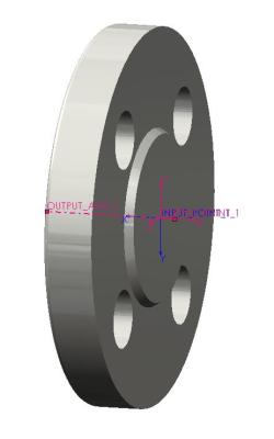
The following requirements apply to ‚finishing components‘ in Smap3D Piping for SOLIDWORKS®, i.e. components which are meant to be built at the ends of pipelines.
Finishing components are, for example, blind flanges, caps, etc.
Only the side where the pipe should end needs an ‚INPUT_POINT‘, an ‚OUTPUT_POINT‘ and an ‚OUTPUT_AXIS‘.
The proper coordinate systems an axes can be created easily using Coordinate System Wizard.
 If such a component is built into a pipeline, a pipe will not be separated to create two pieces of pipe: instead the pipe is cut and closes at the point of this ‚finishing‘ component.
Example:
A blind flange has only one side where the pipe connects.
This component has only one input and one output option.
This is the only side which needs to be given an ‚INPUT_POINT‘, an ‚OUTPUT_POINT‘ and an ‚OUTPUT_AXIS‘.
 The X axis of each coordinate system must always point in the direction of the INPUT or OUTPUT.
Since Plant Design 2016 you can use the Component Wizard for an easy and fast creation of such components:
The Component Wizard
Druck
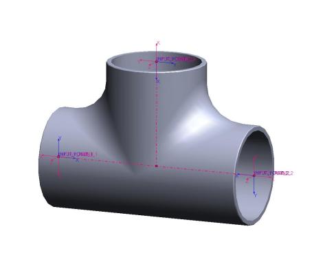
The following requirements apply to ‚flow-through components‘ in Smap3D Piping for SOLIDWORKS®, i.e. for components which are inserted between pipes and through which some medium should flow.
These are components such as ‚bends‘, ‚tees‘, ‚flanges‘, etc.
![]() Each possible connection on a component needs an ‚INPUT_POINT‚, an ‚OUTPUT_POINT‘ and an ‚OUTPUT_AXIS‘.
Each possible connection on a component needs an ‚INPUT_POINT‚, an ‚OUTPUT_POINT‘ and an ‚OUTPUT_AXIS‘.
The proper coordinate systems and axes can be created easily using Coordinate System Wizard.
Example:
A tee has three ways it can be attached to a pipe. Therefore there are three input and three output points.
Each connection must have an ‚INPUT_POINT‘, an ‚OUTPUT_POINT‘ and an ‚OUTPUT_AXIS‘.
This means that a tee prepared for use in Smap3D Piping contains 6 coordinate systems altogether (3x INPUT_POINT and 3x OUTPUT_POINT) and 3 axes (3x Output_AXIS).
![]() The X-axis of each coordinate system must always point in the direction of the INPUT or OUTPUT.
The X-axis of each coordinate system must always point in the direction of the INPUT or OUTPUT.
Since Plant Design 2016 you can use the Component Wizard for an easy and fast creation of such components:
The Component Wizard
Druck