Welcome to Smap3D Plant Design version 2016: What´s new?

With Smap3D Plant Design 2016 we´ve changed the term: From now on the name of the version is based on the year of publication. We also introduce the new Licensing 2016 and lots of new functions and tools. All products and applications contained in Plant Design 2016 are certified for the Windows 10 operating system and can be used with this system.

New Licensing and new Licenses

In the installation package of Plant Design 2016 the new Licensing 2016 is included and must be installed. Due to this change, new license files are required with version 2016. Previous license files are not valid in version 2016. All technical details to the new licensing you can read in the installation guide that is included in the installation package of Smap3D Plant Design 2016.

New in Smap3D P&ID

  • Revised symbol libraries: All previously included symbol libraries have been revised and structured according to MM and INCH. The respective standard names or folder names were expanded with the suffix “_mm” and “_inch”. Due to these changes, the Alias names in the Symbol menu as well as the Pickmenus were adapted and restructured in the user interface.
  • Improvements at work with the INCH unit system: Standard values adapted specifically to INCH are now stored for the pages settings Normal snap, Fine snap and Grid. When drawing lines, converted INCH values are now stored in the list field for the line width. For all types of text, adapted INCH values are now stored as well in the list field for defining the text height.
  • New and enhanced functions to line types: P&ID 2016 contains 5 user-defined line types, which can be selected directly in the list field “Line type”. The “Edit custom lines dialog” contains all relevant functions for creating and managing the user-defined line types (as well as the 5 prepared line types). The general conducting line types (displayed in the selection list without an arrow) were enhanced and can now be displayed with a flow arrow on diagram pages.
  • Improvements to data fields: Smap3D P&ID 2016 has updated the buttons for easier definition of line data fields. For example the user can store a value list for each data field via the “Values” button. If line data fields are defined, these are available on each line in the “Line article data” on the diagram pages. With this feature a user can enter individual values (process characteristics) for each line. The definition of individual symbol data fields is identical to that of the “Line data fields” and is also performed in Settings > Text/Symbol defaults. With Smap3D P&ID 2016 symbol data fields at a symbol can now be adapted individually when used in the project. The management of value lists for all types of data fields is more comfortable – in addition to the already mentioned line and symbol data fields, value lists can also be created and used for many more data fields. Data fields “Name” and “Line” number as needed, recurring value lists (e.g. for fixed TAG numbers) can also be stored for symbols and lines.
  • Improvements to Reference Designations: In the user interface for the Reference designations function, new buttons for Import and Export were added for each aspect. Now individual external tables can be imported and exported without having to take into account all rules for all aspects in a complete table (e.g. aspect prefix). The display of the reference designation for a symbol is now also possible as a separate symbol data field (with all aspects and options) in the diagram.
  • New central folder for format files and value/data lists: The two rows “Data lists” and “Format files” were added as new options for individual and centralized configuration of directories (Settings > Directories).
  • Improvements to the Object groups: When subdrawings are added to a project, they are now automatically converted to an object group. This means that an added subdrawing can continue to be used as an object unit for various operations. Object groups that were automatically created in a diagram by inserting of subdrawings, can be replaced with other subdrawings.The information “Object group” name is now available as a data field for creating lists and reports.

New in Plant Design Administrator

  • New additional standard parts providers: File System and Cadenas PARTSolutions. The new additional standard parts provider File System provides the opportunity to use proprietary standard and supplier parts directly from the Windows file system with Smap3D Plant Design 2016, WITHOUT having to register these beforehand in the PartFinder 9.6 standard parts administrator. Cadenas PARTSolutions provides the opportunity to use proprietary and supplier parts directly from Cadenas PARTSolutions with Smap3D Plant Design 2016 as well, WITHOUT having to register these beforehand in the PartFinder 9.6 standard parts administrator.
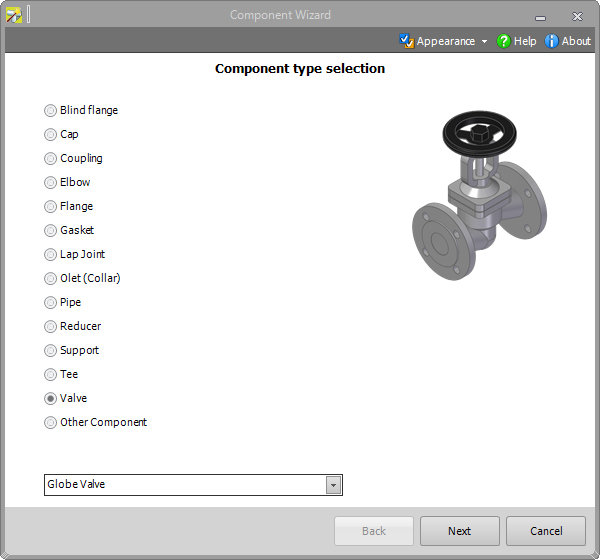
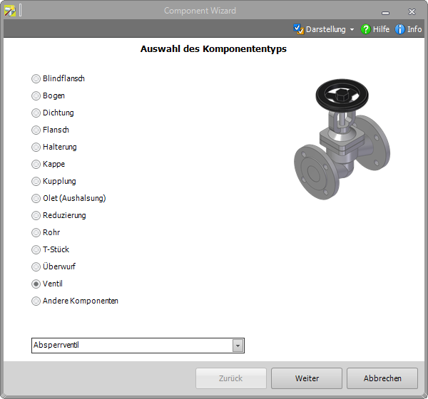
  • New Component Wizard: This new assistant guides a user comfortably through the necessary steps for making a component for Smap3D Plant Design from a standard CAD 3D model. A CAD part file is interactively processed in multiple steps with the required connection point definitions and file properties so that it is immediately available for use with the new additional standard parts administrator File System.

New in Smap3D Pipe Specification Editor

  • Use of additional standard parts provider: If the use of additional standard part providers is activated in Plant Design Administrator, they are available in the Pipe specifications editor as additional buttons for selecting parts (otherwise only PartFinder).
  • Cadenas PARTSolutions: The Cadenas PARTdataManager starts with the button in the Cadenas PARTSolutions column. The search and selection of a required component takes place only via native PARTSolutions functions.
  • Further news to Pipe Specification Editor: New setting in “Options tab”, e. g. the function “Do not place flanges on connected ends automatically” can be activated at any time. Or a new QuickPlace method now offers the opportunity to automatically place a Shape gasket between Shape pipes.

New in Smap3D Piping

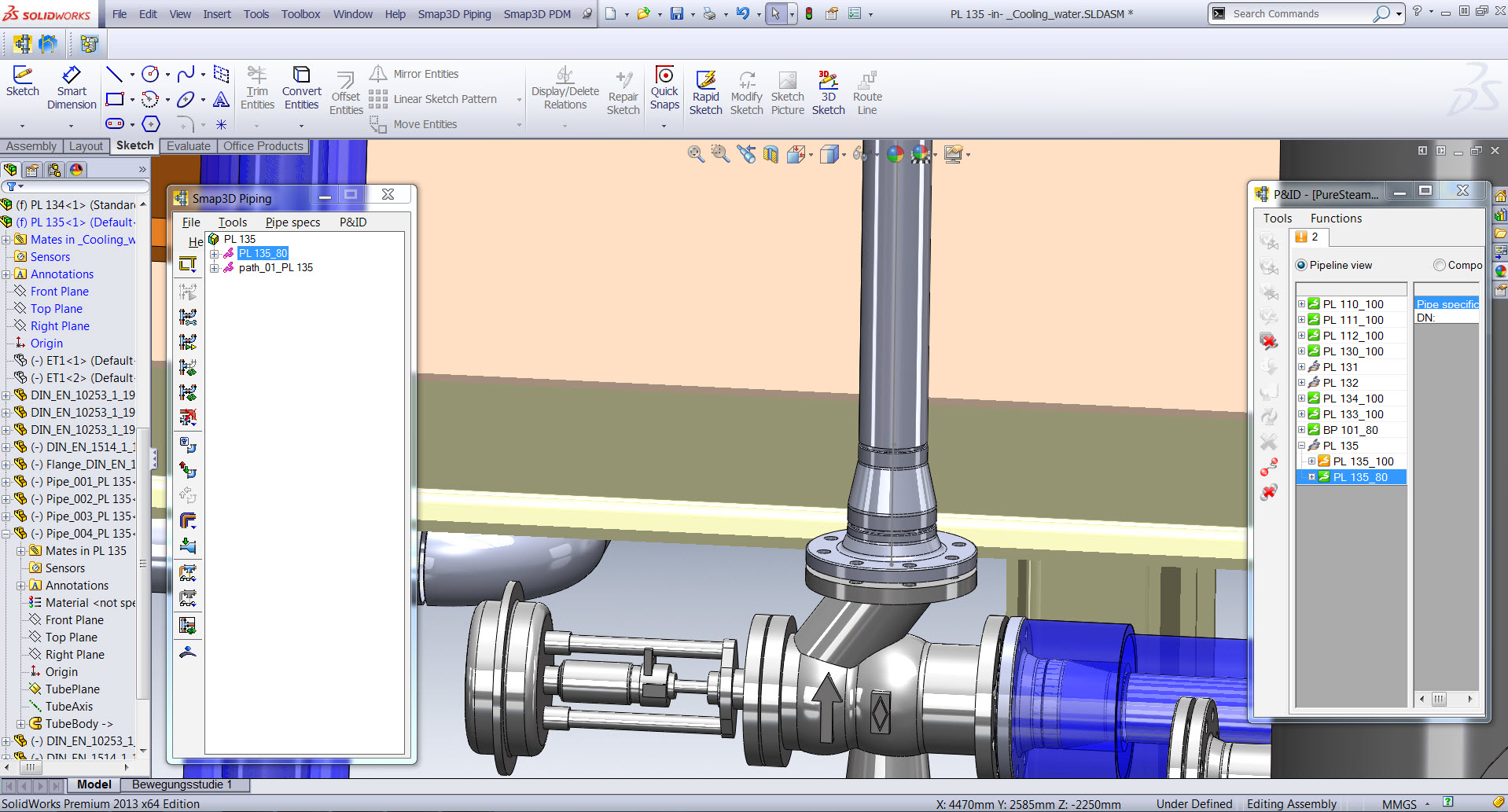
  • New components in the Piping structure tree display: All types of components that contain CO_ORDS coordinate system definitions are displayed. Support components which were manually added to a pipeline or added via the “Place component pattern” function now appear in the structure tree. Furthermore, split-point components are also displayed now.
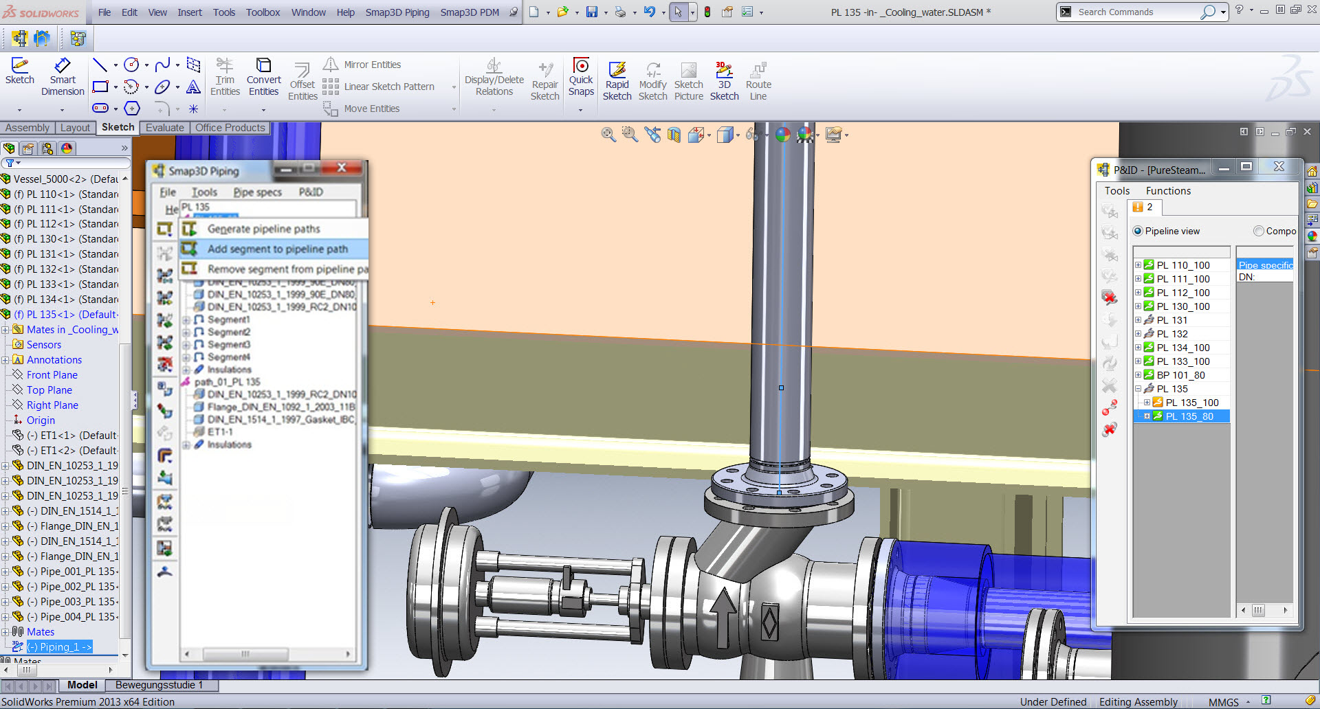
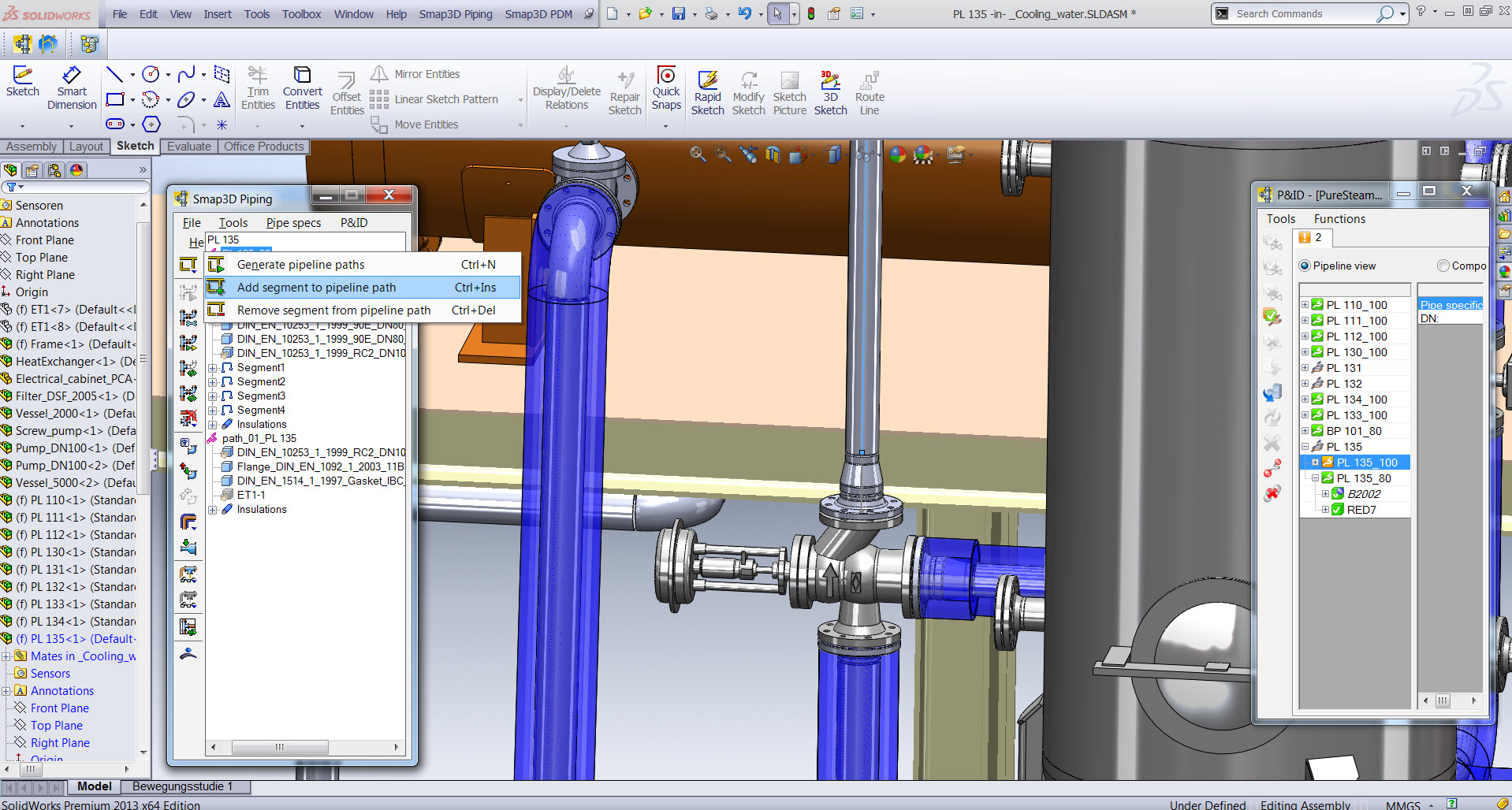
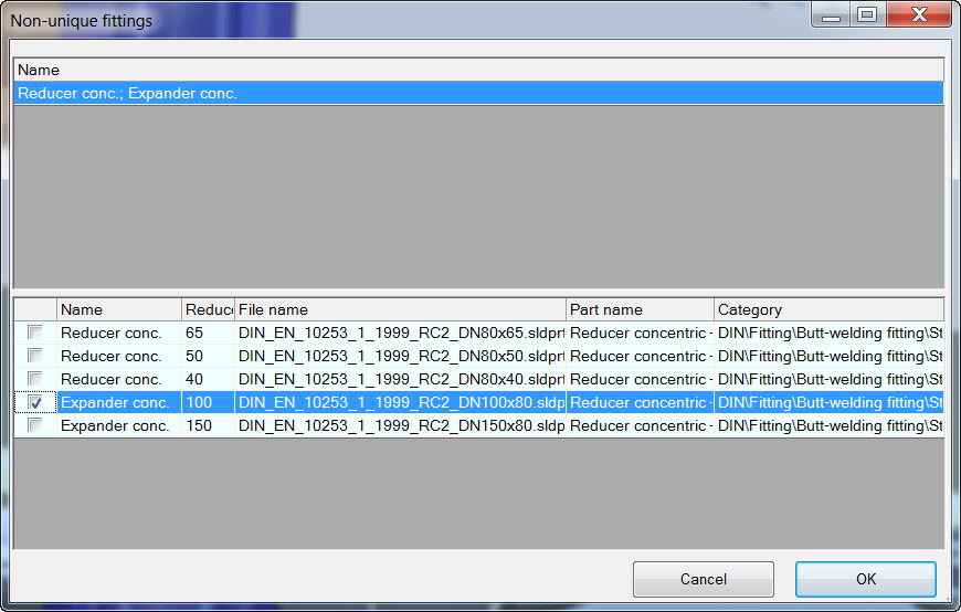
  • Improvements of existing Piping automations: With the enhancement of the Piping structure tree display support components are now also taken into account with the “Edit pipeline” function. The “Recalculate pipeline” function can be used quickly and easily. “Recalculate pipeline” identifies missing concentric components at the connection points between generated pipelines and places the appropriate concentric component from the pipe specification used. The appearance of the dialog “Non-unique components” can now be suppressed/switched off through the “Use favorites” option. For the “Refresh all subassemblies” function, an individual selection now can be made as to whether only certain subassemblies should be updated.
  • Further news to plausibility check: If a violation against the minimum pipe length defined in the pipe specification is determined in the Piping functions “Generate pipeline, Recalculate pipeline, Edit pipeline and Refresh” the defined value from the pipe specification as well as the value identified in the pipeline will now be indicated. The plausibility check also differentiates whether there is a positive or negative gap between the fittings (connection points). If multiple violations are identified simultaneously, the notification is expanded and every instance of a violation is separated from the previous notification with a divider line. For some time now, a plausibility check for closed loops and overlapping line elements has been performed when using the “Generate pipeline path” function. New in Piping 2016 is the graphical feedback (highlight), to show which of the existing line elements are affected by this.

New in the P&ID To-Do list

  • New plausibility check for redundant components: If this option is activated, each time the functions “Generate pipeline, Recalculate pipeline, Edit pipeline and Refresh” are used, Piping will check (only in cooperation with the To-Do List) whether there are more 3D components placed in the active 3D pipeline than specified by the P&ID. If a violation is identified, the associated notification will display the name of the redundant component as well as the name of the affected pipeline.
  • Use of the P&ID line data fields: The line data fields in a Smap3D P&ID project can now also be used in the To-Do list. The use of line data fields is activated in the To-Do List options.
  • Direct access to standard parts providers for placing components to CAD: If a user selects a component in the To-Do List and starts the function “Place fitting to CAD” a check is performed as to whether a P&ID ID is saved in the pipe specification so that the component can be automatically placed and assigned. If this not the case, the “Standard parts provider” dialog appears. Depending on the settings in Plant Design Administrator, a user has direct access to the available standard parts providers here. After selecting a standard parts provider and clicking “OK”, this standard parts provider starts and from there a user can place the desired components in the active 3D assembly by way of the contained functions.
Druck Druck

Smap3D Plant Design 2016: Ausgewählte Neuerungen

Mit der neuen Version von Smap3D Plant Design hat sich nicht nur die Bezeichnung für die Version verändert, die nun unter Angabe des Erscheinungsjahres erfolgt. Auch ein neues Licensing und viele neue Funktionen bereichern Smap3D Plant Design 2016. Alle darin enthaltenen Produkte und Applikationen sind für das Betriebssystem Windows 10 zertifiziert und können damit betrieben werden.

Neues Licensing und neue Lizenzen

Mit der neuen Version “Smap3D Plant Design 2016” wird das neue Licensing 2016 eingeführt, das installiert werden muss. Aufgrund dieser Umstellung werden neue Lizenzen benötigt. Die Lizenzen aus vorherigen Versionen verlieren ihre Gültigkeit.

Neu in Smap3D P&ID

  • Überarbeitete Symbolbibliotheken: Die bisher enthaltenen Symbolbibliotheken wurden überarbeitet und nach MM und INCH strukturiert. Die jeweiligen Norm- bzw. Ordnernamen wurden mit den Bezeichnungen _mm und _inch erweitert. Auch die Alias-Namen im Symbolmenü sowie die Pickmenüs in der Benutzeroberfläche sind angepasst und umstrukturiert.
  • Erweiterungen beim Arbeiten mit dem INCH-Einheitensystem: Für die Seiteneinstellungen “Normaler Fang, Feiner Fang und Gitter” sind nun spezifische auf INCH angepasste Standardwerte hinterlegt. Auch beim Zeichnen von Linien sind die angepassten INCH-Werte im Listenfeld für die Linienbreite enthalten. Ähnliches gilt für alle Arten von Texten, bei denen die angepassten INCH-Werte im Listenfeld für die Definition der Texthöhe entnommen werden kann.
  • Neue und erweiterte Funktionen zu Linienarten: Es wurden 5 benutzerdefinierte Linienarten integriert, die direkt im Listenfeld Linienart ausgewählt und verwendet werden können. Der Dialog “Linienerzeugung” enthält dabei alle relevanten Funktionen zur Erzeugung und Verwaltung der benutzerdefinierten Linienarten (auch der 5 integrierten). Die allgemeinen leitenden Linienarten (werden in Auswahlliste ohne Pfeil angezeigt) wurden erweitert und können auf Diagrammseiten auch mit Flusspfeil dargestellt werden.
  • Neuerungen bei den Datenfeldern: Es werden neue Schaltflächen für eine einfachere Definition von Liniendatenfeldern angeboten. So kann z. B. über die Schaltfläche “Werte” zu jedem Datenfeld eine Werteliste hinterlegt werden. Sind Liniendatenfelder definiert, so sind diese auf Diagrammseiten an jeder Linie in den Liniendaten verfügbar. Ein Anwender kann damit für jede Linie individuelle Werte (Prozesseigenschaften) eingeben. Die Definition von individuellen Symboldatenfeldern ist identisch zu den Liniendatenfeldern und erfolgt ebenso in den Einstellungen > Text-/Symbolstandards. Auch diese wurden um Schaltflächen ergänzt. Ab dieser Version können Symboldatenfelder an einem Symbol nun auch individuell bei der Verwendung im Projekt angepasst werden. Bezüglich der Wertelisten wurden deren Handhabung für alle Arten von Datenfeldern vereinheitlicht.Neben den Linien- und Symboldatenfeldern können Wertelisten auch für viele weitere Datenfelder erzeugt und verwendet werden. Auch für die Datenfelder “Name:” und “Leitungsname:” bei Symbolen und Linien kann man bei Bedarf wiederkehrende Wertelisten (z.B. fixe TAG Nummern) hinterlegen.
  • Neuerungen zu Referenzbezeichnungen: In der Benutzeroberfläche der Funktion “Referenzbezeichnungen” wurden neue Schaltflächen für den Import und Export pro Aspekt hinzugefügt. Damit können nun individuelle externe Tabellen importiert und exportiert werden, ohne in einer kompletten Tabelle alle Regeln für alle Aspekte (z.B. Aspektpräfix) beachten zu müssen. Die Darstellung der Referenzbezeichnung für ein Symbol ist nun auch als separates Symboldatenfeld (mit allen Aspekten und Optionen) im Diagramm möglich.
  • Neue zentrale Ordner für Formatdateien und Werte-/Datenlisten: Als neue Optionen für eine individuelle und zentrale Konfiguration von Verzeichnissen (Einstellungen > Verzeichnisse) sind die beiden Zeilen “Datenlisten” und “Formatdatei” hinzugekommen.
  • Neuerungen zu den Objektgruppen: Werden Teilzeichnungen (Subdrawings) in ein Projekt eingefügt, so werden diese automatisch in eine Objektgruppe konvertiert. Das bedeutet, dass eine eingefügte Teilzeichnung weiterhin als Objekteinheit für verschiedene Operationen gehandhabt werden kann. Objektgruppen, die durch das Einfügen von Teilzeichnungen automatisch in einem Projekt erzeugt wurden, können mit anderen Teilzeichnungen ersetzt werden. Die Information “Name der Objektgruppe” ist nun als Datenfeld für die Erstellung von Listen und Reports verfügbar.

Neu im Plant Design Administrator

  • Zusätzliche Normteilverwaltungen: File System und Cadenas PARTSolutions. Das File System bietet die Möglichkeit, eigene Standard- und Wiederholteile direkt aus dem Windows-Dateisystem mit Smap3D Plant Design 2016 zu verwenden, OHNE diese zuvor in die PartFinder 9.6 Normteilverwaltung einpflegen (registrieren) zu müssen. Mit Cadenas PARTSolutions können Standard- und Wiederholteile direkt aus Cadenas PARTSolutions ebenfalls mit Smap3D Plant Design 2016 (ohne den PartFinder 9.6) verwendet werden.
  • Component Wizard: Dieser neue Assistent führt einen Anwender komfortabel durch die notwendigen Schritte, um aus einem normalen Modell eine Komponente für Smap3D Plant Design zu machen. Dabei wird eine Einzelteildatei aus dem CAD in mehreren Schritte interaktiv mit den benötigten Anschlusspunktdefinitionen und Dateieigenschaften aufbereitet, um diese im Anschluss direkt für die neue zusätzliche Normteilverwaltung File System zur Verfügung zu stellen.

Neu im Smap3D Pipe Specification Editor

  • Verwendung der zusätzlichen Normteilverwaltungen: Wurde im Plant Design Administrator die Verwendung der (neuen) zusätzlichen Normteilverwaltungen aktiviert, so stehen im Pipe Specification Editor (Rohrklasseneditor) diese als weitere Schaltflächen für die Auswahl von Teilen zur Verfügung (ansonsten nur PartFinder).
  • Cadenas PARTSolutions: Mit der Schaltfläche in der Spalte “Cadenas PARTSolutions” startet der Cadenas PARTdataManager. Die Suche und Auswahl einer benötigten Komponente erfolgt mit nativen PARTSolutions Funktionen.
  • Neuerungen im Rohrklasseneditor: Neue Einstellungen im Register “Optionen”, z. B. Die Funktion “Flansche an verknüpfte Leitungsenden nicht automatisch platzieren” kann bei Bedarf aktiviert werden. Auch stehen sowohl im Rohrklasseneditor und als auch im Smap3D Piping die neue QuickPlace Methode “Formdichtung” zur Verfügung. D. h. man kann zwischen Formrohren automatisch eine Formdichtung platzieren.

Neu in Smap3D Piping

  • Neue Komponenten in Piping Strukturbaumanzeige: Es werden nun auch alle Arten von Komponenten angezeigt, welche die CO_ORDS Koordinatensystemdefinition enthalten. Zum einen erscheinen nun “Support”-Komponenten im Strukturbaum, die manuell oder über die Funktion “Muster platzieren” zu einer Rohrleitung hinzugebaut wurden. Zum anderen werden nun auch “Split-Point”-Komponenten angezeigt.
  • Erweiterungen zu den bestehenden Piping Automatismen: Mit Erweiterung der Piping Strukturbaumanzeige werden “Support”-Komponenten nun auch mit der Funktion “Rohrleitung bearbeiten” berücksichtigt. Die neue Funktion “Rohrleitung neu berechnen” erkennt jetzt fehlende konzentrische Komponenten an den Verbindungspunkten zwischen generierten Rohrleitungen und platziert die passende konzentrische Komponente aus der verwendeten Rohrklasse. Das Erscheinen des Dialogs “Nicht eindeutige Komponenten” kann man ausschalten, indem die Option “Favoriten” verwendet wird. Bei der Funktion “Alle Unterbaugruppen aktualisieren” ist es nun möglich, eine individuelle Auswahl zu treffen, wenn nur bestimmte Unterbaugruppen aktualisiert werden sollen.
  • Neuerungen der Plausibilitätsprüfung: Wird bei den Piping Funktionen “Rohrleitung generieren, Rohrleitung neu berechnen, Rohrleitung bearbeiten und Aktualisieren” ein Verstoß gegen die in der Rohrklasse eingestellte minimale Länge von Rohren festgestellt, so wird in der Meldung der festgelegte Wert aus der Rohrklasse sowie der in der Rohrleitung erkannte Wert angezeigt. Bei der Rückmeldung der Plausibilitätsprüfung wird auch unterschieden, ob es sich um eine positive oder eine negative Lücke zwischen den Fittings (Anschlusspunkten) handelt. Werden gleichzeitig mehrere Verstöße festgestellt, so wird die Meldung erweitert und jeder gemeldete Verstoß durch Trennstriche von der vorherigen Meldung getrennt. Bei der Ausführung der Funktion “Rohrleitungspfade generieren” wird schon seit langem eine Plausibilitätsprüfung gegen geschlossene Schleifen (Loops) und überlappende Linienelemente durchgeführt. Neu ist die grafische Rückmeldung (Markierung) im CAD-Arbeitsfenster, welche der Linienelemente davon betroffen sind.

Neu in der P&ID To-Do Liste

  • Neue Plausibilitätsprüfung auf “überzählige Komponenten”: Wird diese Option aktiviert, so prüft Piping (nur im Zusammenspiel mit der To-Do Liste) jedes Mal bei Ausführung der Funktionen “Rohrleitung generieren, Rohrleitungen neu berechnen, Rohrleitungen bearbeiten und Aktualisieren”, ob in der aktiven 3D Rohrleitung mehr 3D Komponenten eingebaut sind, als dies vom P&ID her vorgegeben ist. Wird ein Verstoß festgestellt, so wird in der dazugehörigen Meldung der Name der überzähligen Komponente sowie der Name der betroffenen Rohrleitung angezeigt.
  • Verwendung der P&ID Liniendatenfelder: Die in einem Smap3D P&ID Projekt vorhandenen Liniendatenfelder können nun auch in der To-Do Liste verwendet werden, wenn in den To-Do Listen Optionen die Verwendung von Liniendatenfeldern in der To-Do Liste aktiviert wird.
  • Direkter Zugriff auf Normteilverwaltungen für Komponente in CAD platzieren: Wählt ein Anwender in der To-Do Liste eine Komponente und startet die Funktion “Komponente in CAD platzieren”, so wird weiterhin geprüft, ob in der Rohrklasse eine P&ID ID hinterlegt ist, damit die Komponente automatisch platziert und zugewiesen werden kann. Ist dies aber nicht der Fall, so erscheint nun der Dialog “Normteilverwaltung”. Je nachdem was im “Plant Design Administrator” eingestellt ist, hat ein Anwender hier direkten Zugriff auf die verfügbaren Normteilverwaltungen und kann von dort die gewünschte Komponente durch die enthaltenen Funktionen in die aktive 3D Baugruppe platzieren.


Druck Druck

Inserting a reducer

How do you add a reducer to your pipeline.

In the following you will find detailed instructions on how to add a reducer to a pipeline.

1st you must edit the 3D sketch in SOLIDWORKS, right click on it and select “split point”. Then click along the sketched line to place a point where the reducer will be inserted. You can add a dimension to locate the point specifically.

Next,

Highlight the pipeline in the piping tree and verify that the entire 3D sketch is highlighted. Depending on the order in which you split the sketch you might have to use the “add Segment” tool.


Then with the pipeline still highlighted in the piping tree, clink on “add concentric component” button and then select the desired size.


In this case you want the 100×80 size.


Then click on the point where the sketch is split (the point filter is automatically turned on)


the reducer is inserted and the pipeline is automatically recalculated to update the pipeline.


Druck Druck