Adjusting your ISO orientation for SOLIDWORKS

In the past it was necessary to build your SOLIDWORKS Assembly in an unorthodox view orientation so that your Single Line Isometric Drawings (ISOGEN) would be in the correct orientation. Well a couple of releases back we have resurrected that situation. There is now more options for you to freely control the output of you ISO drawings without doing anything more than choosing a different option from the Smap3D Isometric settings menu. Let’s look at exactly where this setting is.

Go to Start, All Programs, CAD Partner, Smap3D Plant Design, and click on Isometric.


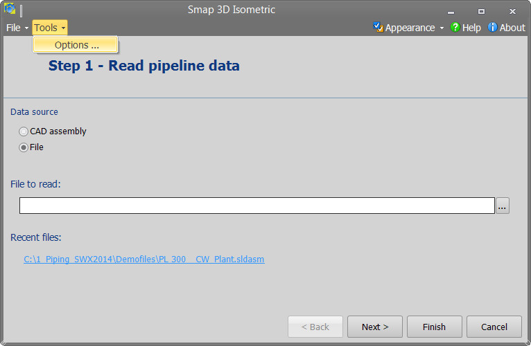
With Smap3D Isometric open you now have access to open the options, which is in the Tools pull-down menu.

Open ISO options

From here you have access to change the “Up/North direction”. Notice all of the options that are available now.

New available direction settings

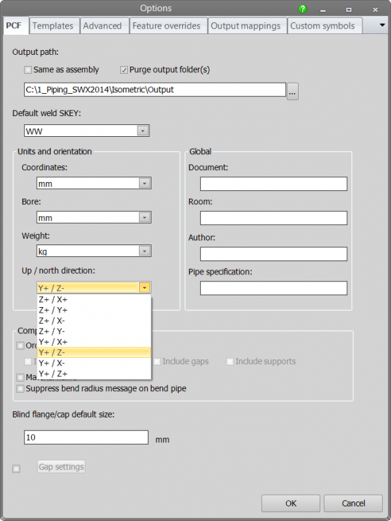
Below you will see the preferred setting for use with SOLIDWORKS.

Correct setting for SolidWorks

Druck Druck

Conversion of Smap3D standard and repetition parts for SOLIDWORKS 2015

In SOLIDWORKS 2015, there is a breaking change causing 3rd party data loss when saving a document with SOLIDWORKS 2015.
Smap3D applications use this 3rd party data storage streams to hold some information.

Therefore it is important and inevitable to perform the Smap3D parts conversion with the Smap3D SOLIDWORKS 2015 conversion tool to save Smap3D data storage (standard and repetition parts) before starting to work with Smap3D parts in SOLIDWORKS 2015 or its future versions.

In this PDF document the workflow is described step by step:
Conversion of Smap3D parts for SolidWorks 2015

Video instruction:
Video guide to converter tool for SolidWorks 2015

Druck Druck

Konvertieren von Smap3D Norm- und Wiederholteilen für SOLIDWORKS 2015

Mit SOLIDWORKS 2015 wurde eine grundlegende Änderung in der SOLIDWORKS Dateistruktur vorgenommen.
Diese verursacht, dass Informationen von Drittanbietern in den Dateien verloren gehen, sobald man diese mit SOLIDWORKS 2015 speichert.
Die Smap3D Plant Design Anwendungen nutzten bisher diese Speicherstruktur für Drittanbieter, um für Smap3D Plant Design notwendige Informationen bereitzustellen. Weiterlesen

Druck Druck

Adding Insulation to Smap3D Pipelines

Problem: I need to add insulation to my pipeline, however the “insulation” tool is grayed out. Here are the steps to add insulation to your pipelines in Smap3D.

Solution: Insulation is an property of the pipe spec. 1st we need to enable the insulation option in the pipe spec being used. Open the Pipe Spec Editor and then open the pipe spec you are using. See the image below showing how to go to the “options” tab, check the box to “enable Insulation”, then Save and Close the pipe spec.

Click here to see a detailed video

With the Pipe Spec now modified to include insulation, we are ready to modify the pipeline with Smap3D. Highlight the Pipeline you want to add insulation to in the piping tree. Below I have selected the “PL 130_100”.

Then click on the insulation icon in the Piping toolbar and select “Generate insulation” from the flyout.

A window will pop up asking you how much of the pipeline you wish to insulate. Along the entire pipeline is what I wish to do so I click that button and the system will generate the insulation automatically. Size, color, and transparency are controlled by the insulation settings in the pipe spec.

After it is generated you can control the visibility of the insulation by right clicking the pipeline in the Smap Piping tree and there you will find the options to “Hide insulation(s)” or Show insulation(s)”.

Click here to see a detailed video


#Smap #Piping #Piping in SolidWorks #Pipe insulation

Druck Druck