The Component Wizard is available with Smap3D Plant Design 2016. This assistant guides a user comfortably through the necessary steps for making a component for Smap3D Plant Design from a standard CAD 3D model.
A CAD part file is interactively processed in multiple steps with the required connection point definitions and file properties, so that it is immediately available for use with the new additional standard parts administrator File System.
First steps with the Component Wizard
- By default, it is always available in the Windows Start Menu CAD-Partner > Smap3D Plant Design 2016 > Admin Tools.
- If Smap3D Toolbars (from within the Plant Design Administrator) are installed, the associated button can be accessed in the “part”-environment of your CAD.
- When creating or editing pipe specifications in the Pipe Specification Editor with an active File System standard parts provider, the user is asked if he wants to use an existing Plant Design component or prepare a new one with the Component Wizard
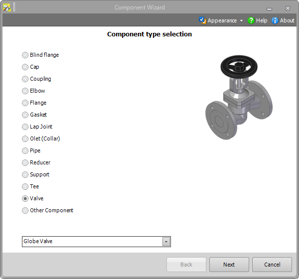
1. Selecting the component type
In the first step, the user must select which component type corresponds to the active CAD 3D model.
Tip: In the first version of the Component Wizard are only part files supported. For assemblies we recommend to use the Coordinate System Wizard.
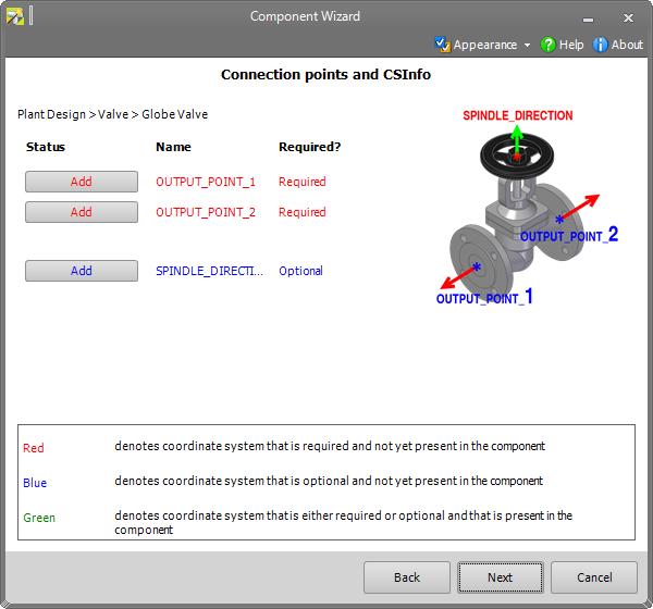
2. Connection points and CS Info
Next, the necessary connection point definitions must be created for the selected component type.
The respective “Coordinate System Wizard” is started with the “Add” buttons. The available options are each filtered on the corresponding parameters in accordance with the selected component type and the respective connection (connection number).
With the “Coordinate System Wizard” a user must create the respective connection point definitions (coordinates system and CS Info property) in the 3D model.
PLEASE NOTE THE RESPECTIVE CONNECTION NUMBER. THIS MUST BE ATTACHED TO THE CORRESPONDING GEOMETRY OR POSITION IN THE 3D MODEL.
Tip: Click Next only after all connection point definitions (interfaces) are displayed in green.
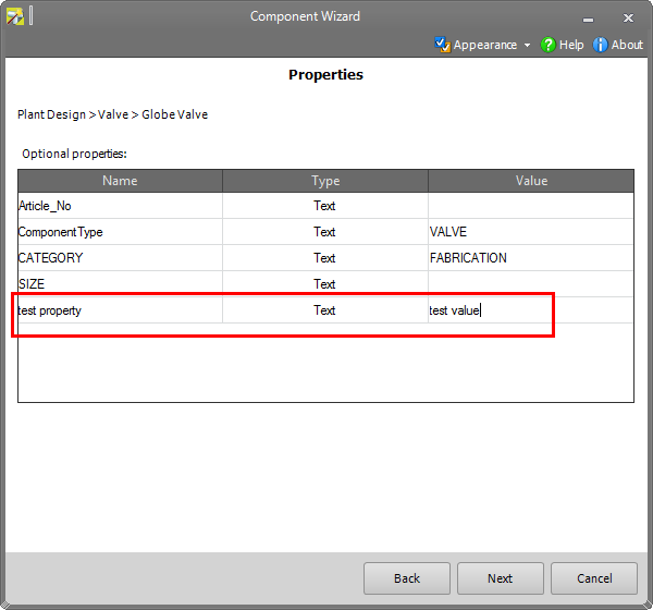
3. Properties
In this step, the “required” and/or “optional standard properties” are displayed in accordance with the component type. If “required properties” are displayed, a user must enter the corresponding values for these. “Optional properties” can theoretically remain empty, but we recommend adding as much information as possible for the components so that these are also ready for any future needs.
In addition to the optional properties displayed by default, further optional properties can be created (the functions for this are in the context menu).
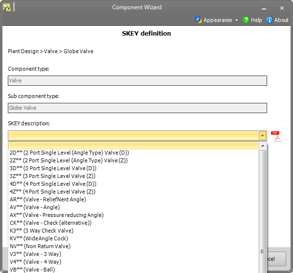
4. SKEY definitions
The SKEY definition for the components can be performed in the next step (only required for Smap3D Isometric). A filtered list with possible SKEY values is available for each component type. An SKEY definition is optional. If you are not using Smap3D Isometric, this property can remain empty.
5. Save component
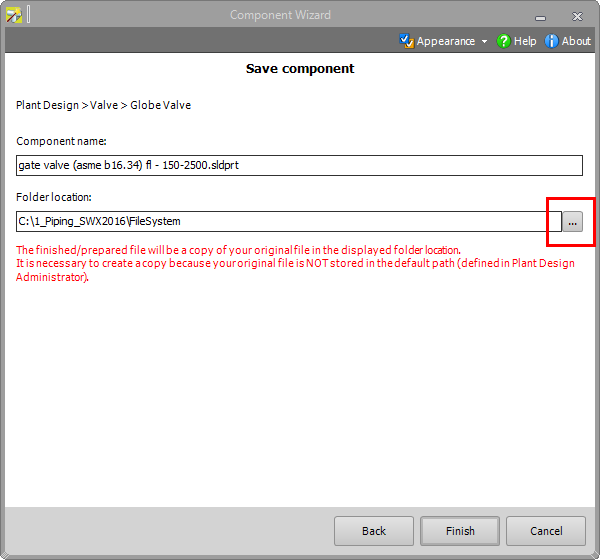
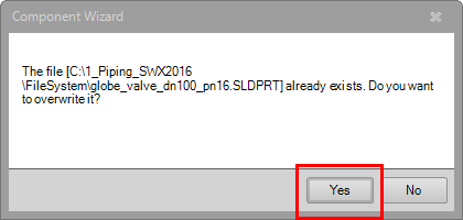
The processed component is saved in the last step. If the active 3D part file was already saved before processing with the Component Wizard in the standard parts folder for the additional standard parts provider “File System” (or a sub-folder therein) this is displayed in the Folder “location line”. By clicking on the “Finish” button followed by “Yes”, the 3D file is overwritten/replaced at this storage location.
If a storage location for the active 3D part file is recognized outside of the standard parts folder for the additional standard parts provider “File System”, an additional notification is displayed in red text in the Component Wizard window.
The “location” folder for the standard parts folder for the additional standard parts provider “File System”, set up in Plant Design Administrator, is displayed in the Storage location line. This storage location can be changed to a sub-folder with the button on the right.
By clicking on the “Finish” button, a copy of the active 3D part file will be stored in the established folder location.
Preparation done with the Component Wizard is only available as a copy in this case. The original file (outside of the standard parts folder) is not changed.
