There are two possibilities to create pipeline pathes in Solid Edge®.
1) Using a pipeline path drawn in XpresRoute environment
Draw the required pipeline path with 3D line segments in the XpresRoute environment and afterwards use the function ‘Generate pipeline paths’ in Smap3D Piping.
![]() For easier editing later, it is recommended to set dimensions and geometric relationships to a drawn path before creating a pipeline path.
For easier editing later, it is recommended to set dimensions and geometric relationships to a drawn path before creating a pipeline path.
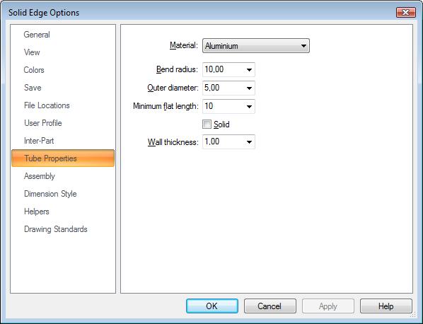
Before the first time usage of the function ‘Generate pipeline paths’ you should check and define the XpresRoute settings for ‘tube properties’ (see picture). With this settings the geometric of the generated pipeline path files are defined.
Tube properties are available only when switched to XpresRoute environment. Since Solid Edge ST you can find it under the ‘Solid Edge Options’ available via the ‘Application Button’.
2) Using a sketch
Create a sketch in the active assembly for the required pipeline. Draw the pipeline path in kind of a 2D sketch (just with lines). Than leave this sketch and change the feature name in PathFinder to the name ‘Piping_XXX‘. The name part ‘Piping_’ is mandatory. Then numbers part ‘XXX’ can free defined.
After that use Piping function ‘Generate pipeline paths’.
![]() For easier editing later, it is recommended to set dimensions and geometric relationships to a drawn path before creating a pipeline path.
For easier editing later, it is recommended to set dimensions and geometric relationships to a drawn path before creating a pipeline path.
Before the first time usage of the function ‘Generate pipeline paths’ you should check and define the XpresRoute settings for ‘tube properties’ (see picture). With this settings the geometric of the generated pipeline path files are defined.
Tube properties are available only when switched to XpresRoute environment. Since Solid Edge ST you can find it under the ‘Solid Edge Options’ available via the ‘Application Button’.
 Only straight lines can be used in Smap3D Piping. Bend segments or curves are not supported, nor are closed loops.
 Before launching the ‘Generate pipeline paths’ function you can use the ‘Delete wrong line segments’ function from ‘Tools’ menu. This function deletes short line segments. The threshold limit can be set between 0 and 10mm.
![]() With launching the ‘Generate pipeline paths’ function a detection of unsupported segment connections starts automatically. If there are some closed loops or overlaid segments drawn in the opened assembly, a warning message will appear and the problematic segments will be highlighted.
With launching the ‘Generate pipeline paths’ function a detection of unsupported segment connections starts automatically. If there are some closed loops or overlaid segments drawn in the opened assembly, a warning message will appear and the problematic segments will be highlighted.